Context & problem
The plant had to bring dust concentration at the precipitator outlet down to the Vietnamese
environmental standard, and the existing equipment could not do it. At the same time, incomplete coal gasification was reducing efficiency and wasting fuel, since the ash still carried a high calorific
value.
This was a pilot: before retrofitting the whole line, the right partner and the right location
for the test module had to be chosen. If the module is placed wrongly, the measurements do not represent the actual system and the retrofit program loses its basis for decisions.
Approach
- Site investigation before any simulation: quantify the actual operating conditions to choose the pilot R.EP location, the step on which the validity of all later data depends.
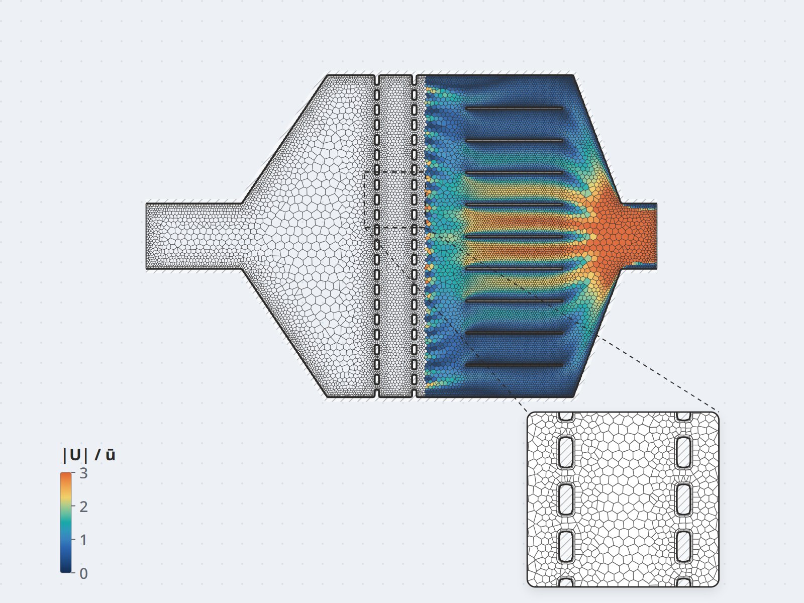
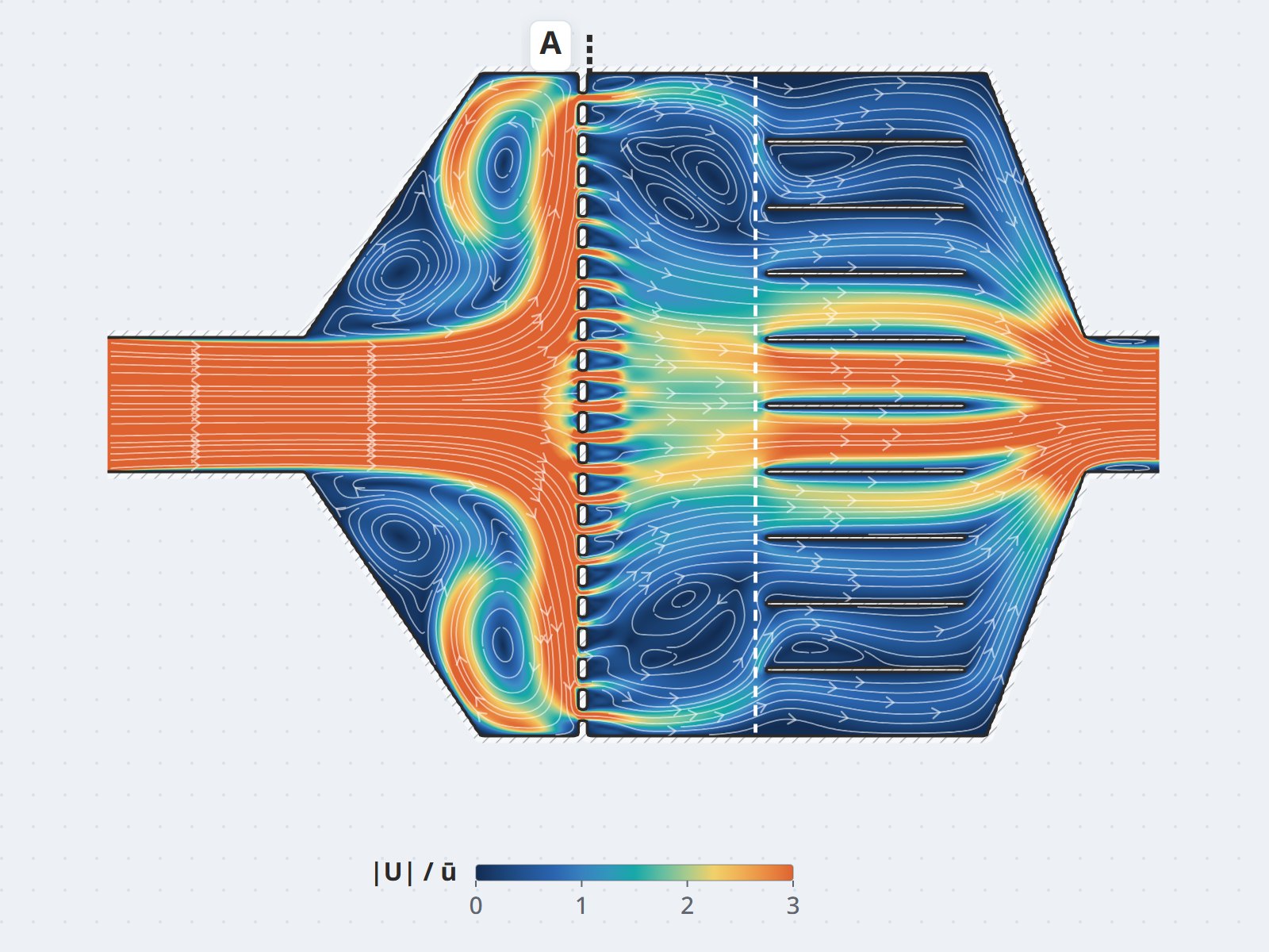
- CFD to locate the bottleneck: model the gas path into the R.EP module and quantify flow quality with a uniformity index (UI).
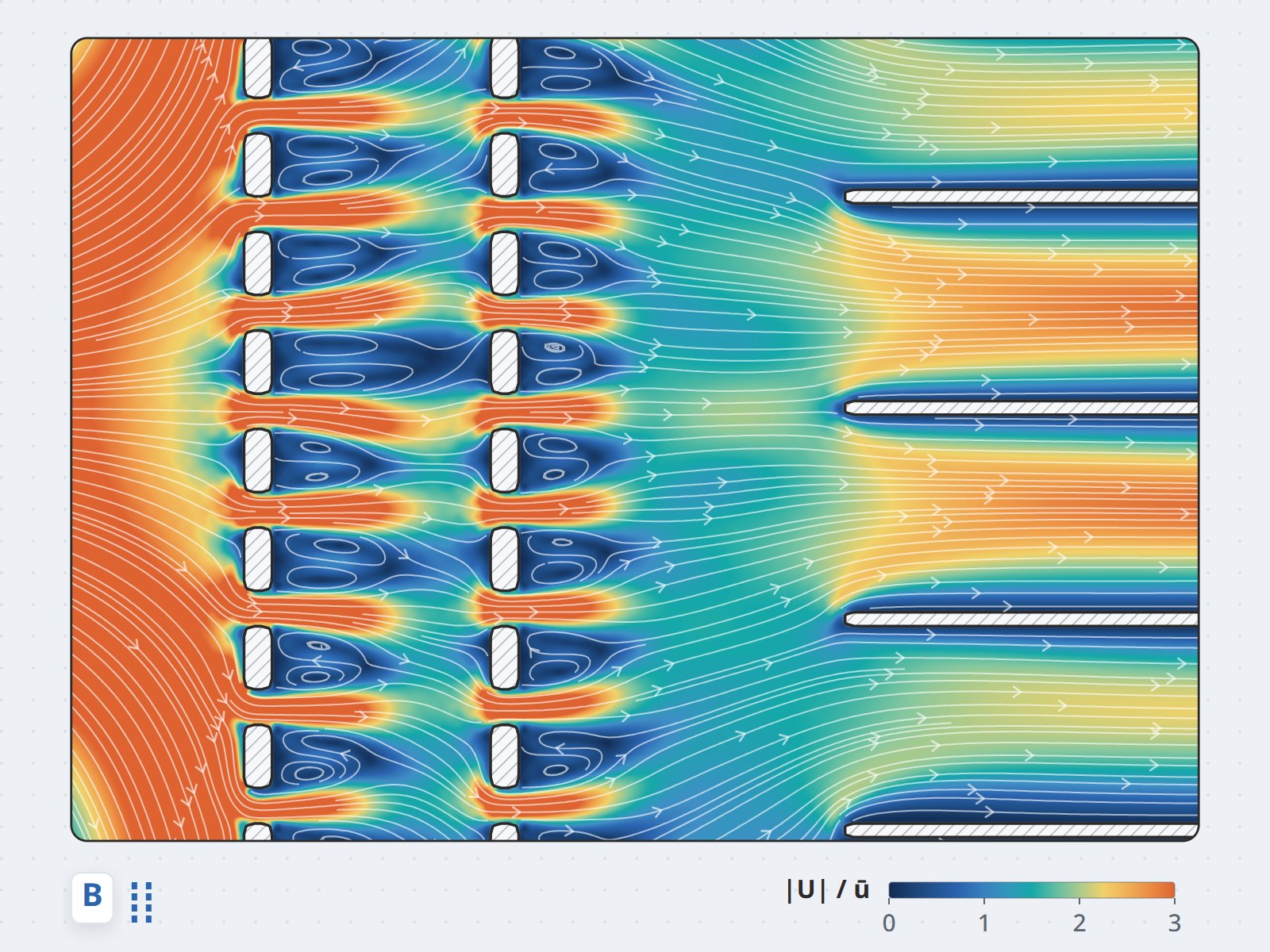
- Distributor screen optimization: compare the base design against an option with a second
perforated plate, scored on the same three measures — peak velocity, uniformity index, standard
deviation.
- Fan selection by calculation: compute the whole-system pressure drop to fix the
fan size, cross-checking hand calculation against simulation at two flow rates.
Results
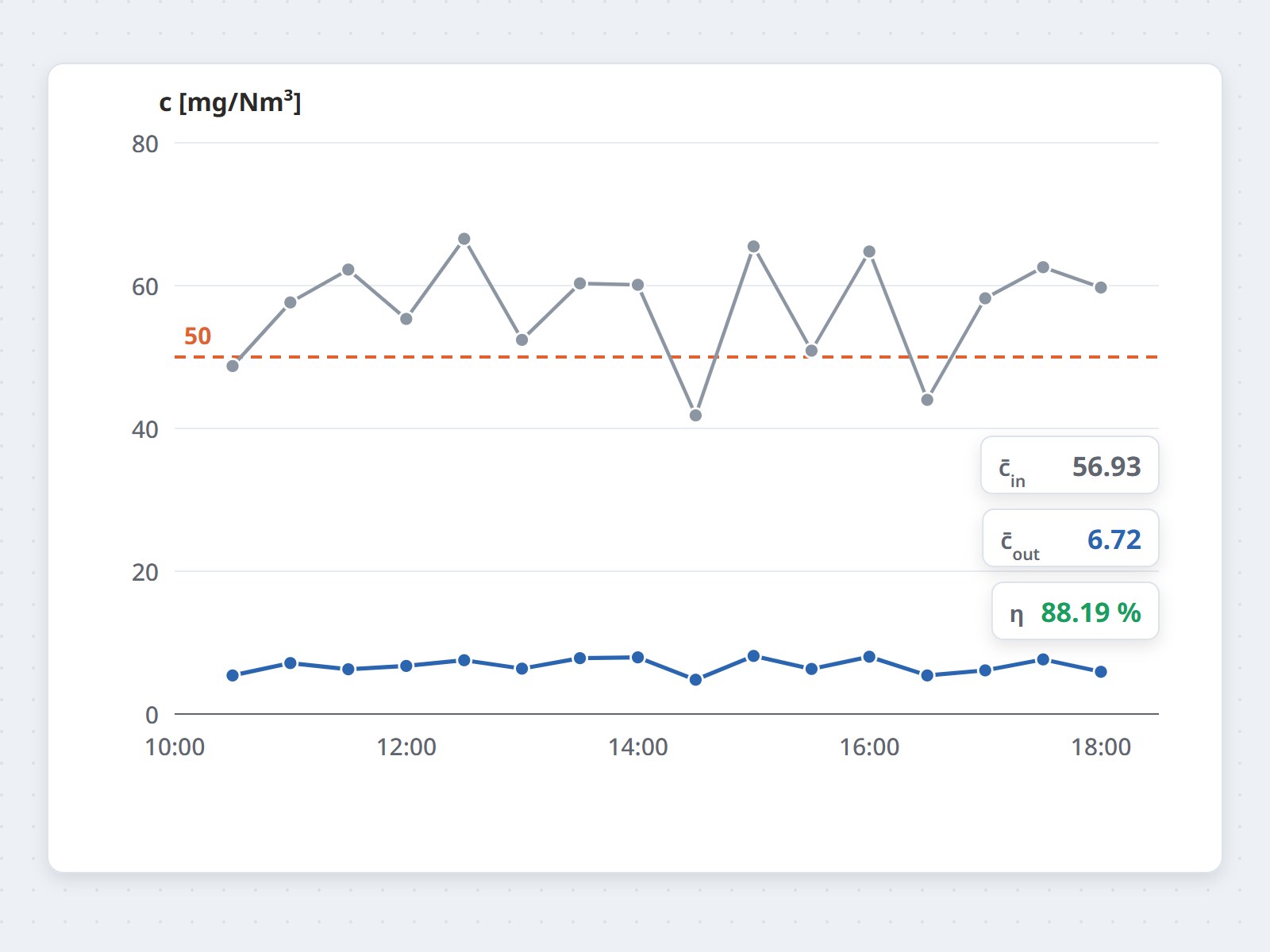
- Pilot measured on site: the R.EP module has run since 03/12/2024, planned for 3 months. Over one
measurement day, dust upstream of the module hovered around 57 mg/Nm³ — above the 50 mg/Nm³ design value of
the precipitator in service — while dust downstream averaged 6.72 mg/Nm³, a collection efficiency of
88.19%.
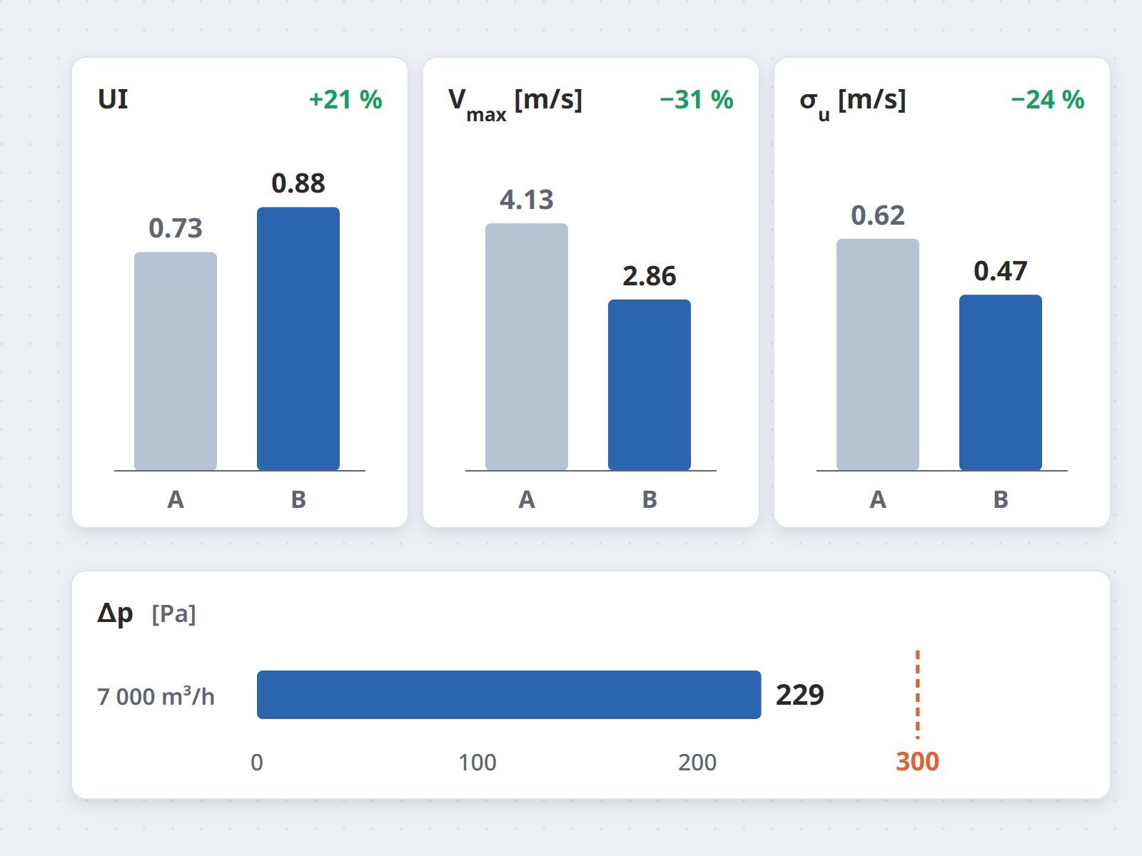
- The distributor screen improved clearly: the flow uniformity index rose from 0.73 to
0.88, peak velocity fell from 4.13 to 2.86 m/s and the standard deviation from 0.62 to
0.47 m/s, while the pressure drop rose only slightly, from 229.85 to 234.81 Pa.
- The bottleneck lay at the module inlet: at the measurement points the flow was
fairly stable (UI = 0.96), but the flow entering the R.EP was poor (UI = 0.72) because of the oversized diffuser, a problem only simulation could reveal.
- Three concrete installation recommendations: keep a 2 m inlet duct for the pilot so the flow
can settle; do not use air guide vanes in small ducts; add guide vanes or a gas distributor port where
flow does need correcting.
- Fan size settled numerically: 900 Pa fan pressure by calculation at 9,000 m³/h and 700 Pa by
simulation at 7,000 m³/h; the simulated pressure drop across the R.EP module came to 229 Pa
against a 300 Pa target.
Value
A pilot is worth its cost only if its data are reliable enough to support decisions on the actual system.
In this project, choosing the location by survey, scoring the distributor screen on three indices and fixing the fan size from the computed pressure drop turned the test module into the engineering basis for the whole retrofit program.