SolutionsPerformance engineering
Pillar 1 · Solutions

Performance engineering

For equipment operating below requirements: energy consumption above design, skewed flow distribution, emissions over the limit, or output stuck at a ceiling. It starts from measurements on the real system.

First step

Equipment performance assessment

Before simulation, the actual operating point of the equipment must be established against design. This is the lowest-cost step and the basis for deciding whether to proceed.

Collecting operating data

Operating logs, on-site readings, design parameters, equipment drawings and piping ISOs. CFDWAYS specifies the minimum list if the data is incomplete.

Heat & mass balance

A balance of the whole system to locate the losses; in many cases the bottleneck lies outside the equipment originally suspected.

The performance gap

The result is quantified: the gap to design, the share recoverable through operation, and the share that requires hardware intervention.

The three-step chain (energy audit → CFD diagnosis → option with KPIs) has been proven in the ceramic tile industry: a spray-drying system paid back in under 2 years (2022–2024 project).

Read the energy efficiency case study →

Energy & process optimization

Most of the wasted energy in a plant lies in how the machines work together under real operating conditions.
  • Operating window: the range of temperature, flow rate and feed ratio that gives the highest efficiency while keeping the equipment safe and staying under the emission limit.
  • Waste-heat recovery: which heat sources are still usable, and which recovery schemes are feasible in terms of both layout and economics.
  • Lower fan and pump consumption: duct pressure losses, flow-guiding devices, the fan operating point — usually the fastest improvement available.
  • KPIs tracked continuously: after the improvement, the indicators go onto a monitoring platform to track whether the gain is sustained over time.

Measured results after retrofit →

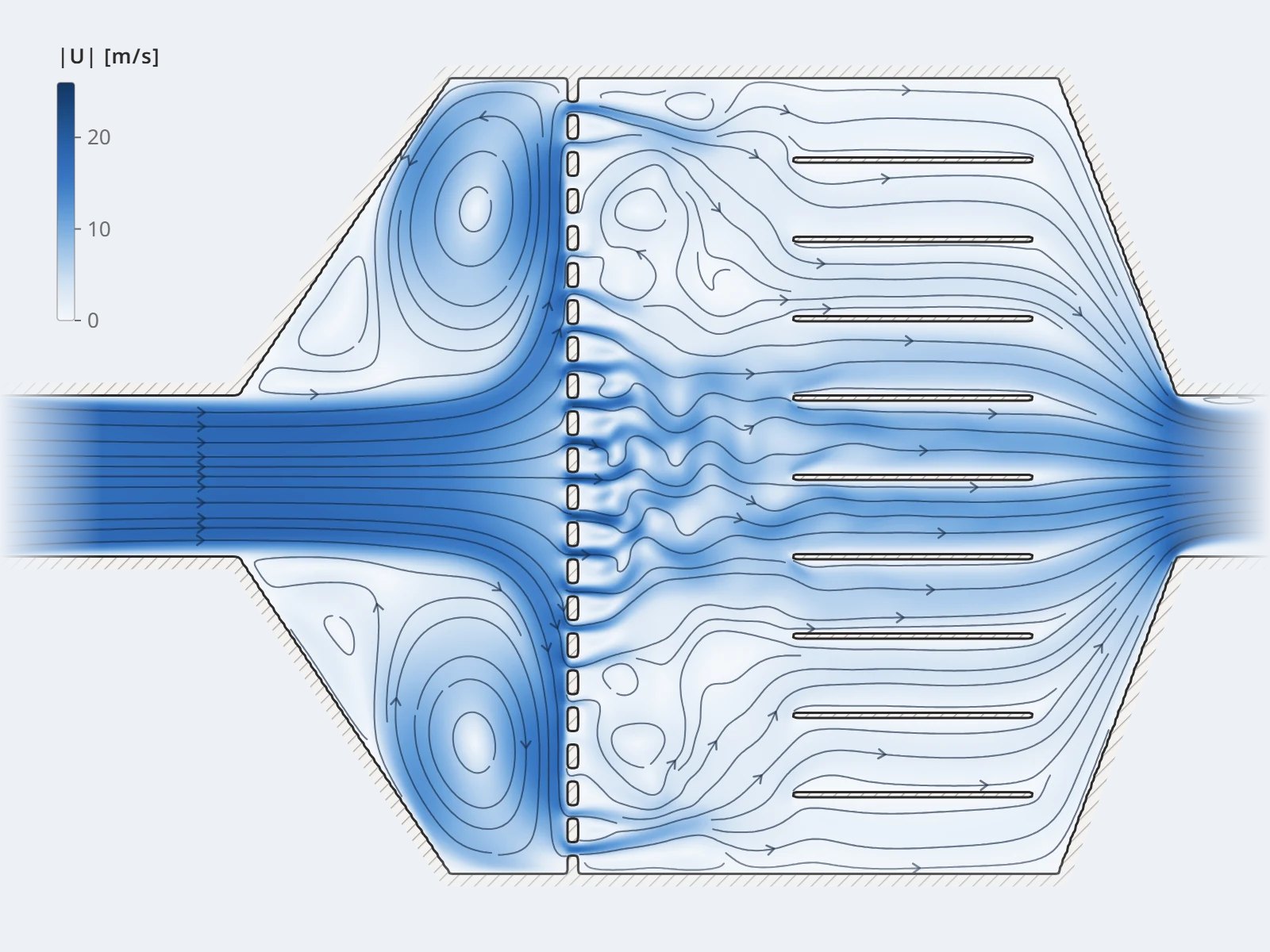
Streamlines and recirculation zones inside equipment — the basis for locating pressure loss
/image/hero-duong-dong.svg4:3 ratio (landscape)
Flow distribution and pressure loss — usually where the wasted energy is recovered fastest.
When measurements alone are inconclusive

Diagnosis & root-cause tracing

Sensors show the outcome, not the cause. Simulation acts as a microscope, revealing zones that no instrument can reach.

Common symptoms

  • Temperature differences between zones inside the same equipment
  • Corrosion or fouling concentrated on one side
  • Pressure loss higher than the design calculation
  • Flue gas treatment underperforming despite sufficient reagent
  • Vibration, localized wear, unusually short material life

How CFDWAYS works

  • Building the model on the real geometry and operating conditions
  • Calibrating against design data or measurements before concluding anything
  • Locating the cause by quantitative criteria, not by impression
  • Separating causes in design, in operation, and in the fuel or feedstock
On the 2022 FGD project, the customer confirmed the model predicted pressure loss to within about 5% of the measurements — reliable enough to serve as the basis for a retrofit.

Read the FGD case study →

From conclusion to hardware

Equipment & system retrofit

This step turns the diagnosis into a concrete hardware change that can be ordered and installed.

Propose the options

A few feasible retrofit options, each stating the scope of intervention and a relative cost estimate.

Verify on the model

Every option is re-run on the same validated model and KPIs compared before/after — the decision rests on data.

Detailed design

Fabrication drawings for the chosen option; manufacturing and supply are carried out with partners.

Post-installation tracking

Measurements after the retrofit are compared with the model prediction, closing the loop and calibrating for later projects.

Talk to us about your equipmentSee capabilities by equipment

Start from the performance gap

Send your current operating parameters and the design parameters. CFDWAYS replies within 24 working hours on the most significant gap and how to verify it.

Send project details