
The greenhouse effect has raised ambient temperatures considerably, with negative consequences for daily life. As the economy grows, the demand for air conditioning to keep living and working spaces comfortable inevitably grows with it. Air conditioning has become an indispensable part of every building, from apartment blocks and commercial buildings to factories, workshops and homes. In Vietnam the air conditioning market is forecast to grow at double-digit rates in the coming years, reaching USD 2.9 billion in 2025 (Research & Markets, 2020).
An air conditioner is a system that removes heat and moisture from an indoor space to keep it comfortable. Its construction and working principle are set out in the figure below.
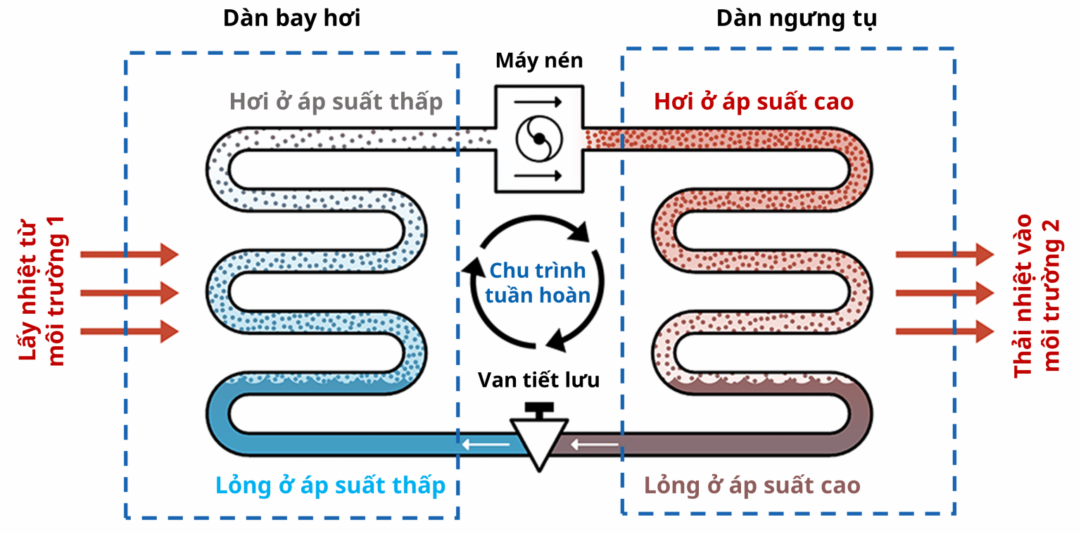
Working principle of an air conditioning system (reference)
In cooling mode the indoor unit absorbs heat to cool the room air, while the condenser unit sits outside rejecting that heat to the environment — so the air leaving the condenser is hotter than the surroundings. If the ambient temperature around the condenser gets too high, heat rejection suffers; in the worst case the unit cannot reject heat at all and shuts down.
Problems after installing condenser units, and how they are solved
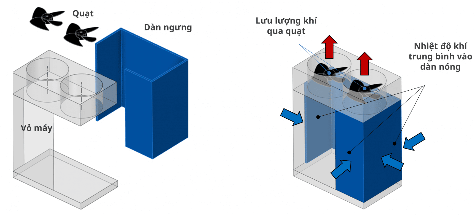
When condenser units sit in open space and reject heat well, the air conditioning works normally. But in buildings with limited installation space, or in particular structures — recessed or enclosed spaces, the light wells of public buildings and apartment blocks — hot air recirculation readily occurs: the air discharged by the condenser does not disperse but returns to its own intake. Recirculation (illustrated below) raises the temperature around the unit. Air conditioning performance falls markedly with ambient temperature — 2–3% for every 1 °C — and once the temperature passes the permitted limit (> 49 °C depending on the unit) the system can shut down; running continuously in those conditions can even damage it. Condenser heat rejection therefore looks like a simple problem but is in practice a difficult one for design engineers.
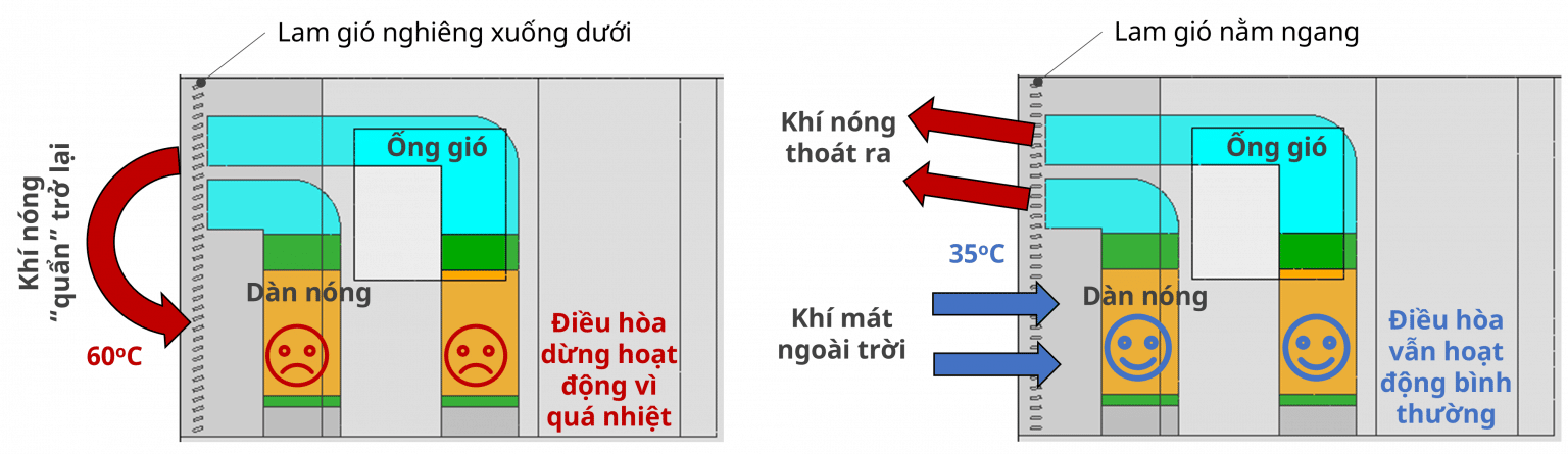
Hot air recirculation (left) and good heat rejection (right)
Recirculation is especially serious in tropical regions, Vietnam among them, where summer ambient temperatures are very high (up to 39–40 °C). Careful condenser placement matters there, so heat rejection works normally, efficiency stays high and electricity consumption falls. The table below summarizes several condenser layouts, the problems they run into and how to deal with them.
| Outdoors, densely packed and close together | Indoors, in a room with limited space | In narrow gaps and light wells | |
|---|---|---|---|
| Characteristics | 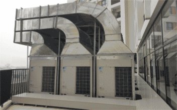 Many condenser units of a central air conditioning system placed close together on the roof or top floor of the building. Many condenser units of a central air conditioning system placed close together on the roof or top floor of the building. | 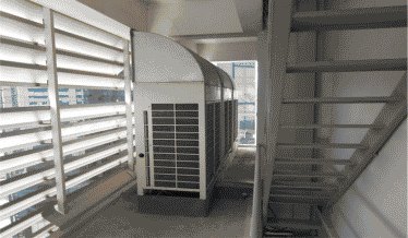 Condenser units placed in a room with limited installation space and little open area for drawing cool air from outside. Condenser units placed in a room with limited installation space and little open area for drawing cool air from outside. | 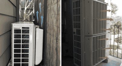 Condenser units placed in narrow gaps and light wells of apartment blocks and high-rise buildings. Condenser units placed in narrow gaps and light wells of apartment blocks and high-rise buildings. |
| Problems after installation |
|
|
|
Problems common to all three layouts:
- Natural wind and surrounding structures trap hot air around the units.
- Solar radiation heats the surrounding structures and the units.
- Heat building up from the units on one floor leaves some of them running inefficiently or unable to run.
- Heat building up between floors leaves the units on upper floors running inefficiently or unable to run.
Solutions:
- Space the units apart and away from surrounding structures.
- Use discharge ducts to collect the hot air and push it away from the intakes: duct height 1 to 3 m, duct angle 10° to 90°.
- Use louvers to redirect the air, at louver angles of 0° to 60°.
Beyond the cases listed in the table there are others: units recessed below floor level discharging upwards, units discharging into each other, units discharging toward the building opposite, units discharging onto passers-by, and so on. Each building faces different problems depending on its actual conditions, so each needs its own solution or set of solutions. Choosing the right one — duct height, deflector angle and so on — is far from easy. Even experienced designers and installers cannot avoid every unforeseen incident, and the consequences are unwelcome: a system that cannot reach capacity, or one that shuts down. To avoid this, many contractors test the design experimentally over a limited scope before construction. At small scale that is not enough to prove feasibility; at large scale it is prohibitively expensive. A number of companies and contractors have therefore turned to a “virtual experiment” instead: computational fluid dynamics (CFD simulation), a faster and cheaper approach than physical testing.
Using CFD to assess condenser unit installation
CFD has many applications in industry generally and in air conditioning and ventilation (HVAC) in particular. Within HVAC it is used to simulate condenser units, which allows a solution to be checked and assessed, then optimized before construction.
Assessment criteria
Because air conditioning performance depends on the ambient air temperature outside the condenser, the CFD work concentrates on the distribution of:
- the temperature around the condenser intake, and
- the air flow rate entering the condenser.
The intake temperature largely decides how well the condenser performs, so the further it is below the critical threshold the better. A reduced air flow into the condenser also lowers the cooling capacity of the machine.
The VRV condenser simulation model and the positions where the results are evaluated
CFD applied to condensers installed in a plant room
To show what CFD offers over other methods, consider the simulation of a densely packed condenser installation in a space-constrained plant room — the most complex case and the hardest to control thermally. The building has four stories, with the top three each containing a condenser room, aligned vertically; each room measures 13×5×3.5 m (length × width × height) and holds 11 high-capacity VRV central air conditioning condensers. The units have ducts and deflector vanes to direct the discharge. The 3D model is shown below.
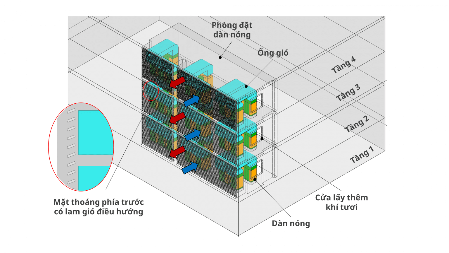
The 3D model used for the simulation
The building was simulated under these conditions:
- A summer ambient temperature averaging 35 °C.
- All condensers running at the same time.
- Natural wind and solar radiation neglected.
CFD was applied to the original design and to a new one:
- Original design: deflector vanes on every floor angled 15 degrees downwards, no windows.
- New design: vanes angled 20 degrees down on floor 2, 5 degrees down on floor 3 and 15 degrees up on floor 4, with windows admitting outdoor air.
The results below show that in the original design the hot discharge tends to fall and is drawn in by the condensers on the floors below. It is particularly severe on floor 3, where the hot air recirculates into the central condenser and raises its intake temperature to 49.5 °C — above the machine's operating limit. Intake temperatures at the other condensers on floors 2 and 3 are also high enough to cut performance and risk a shutdown. In the new design the discharge disperses away from floor 3, so the intake temperature of that central condenser falls considerably (from 49.5 °C to 41 °C), and the intake temperature of every condenser lies within the operating window the manufacturers recommend for VRV or VRF systems (Daikin 49 °C, LG 48 °C). The chart below shows this more clearly.
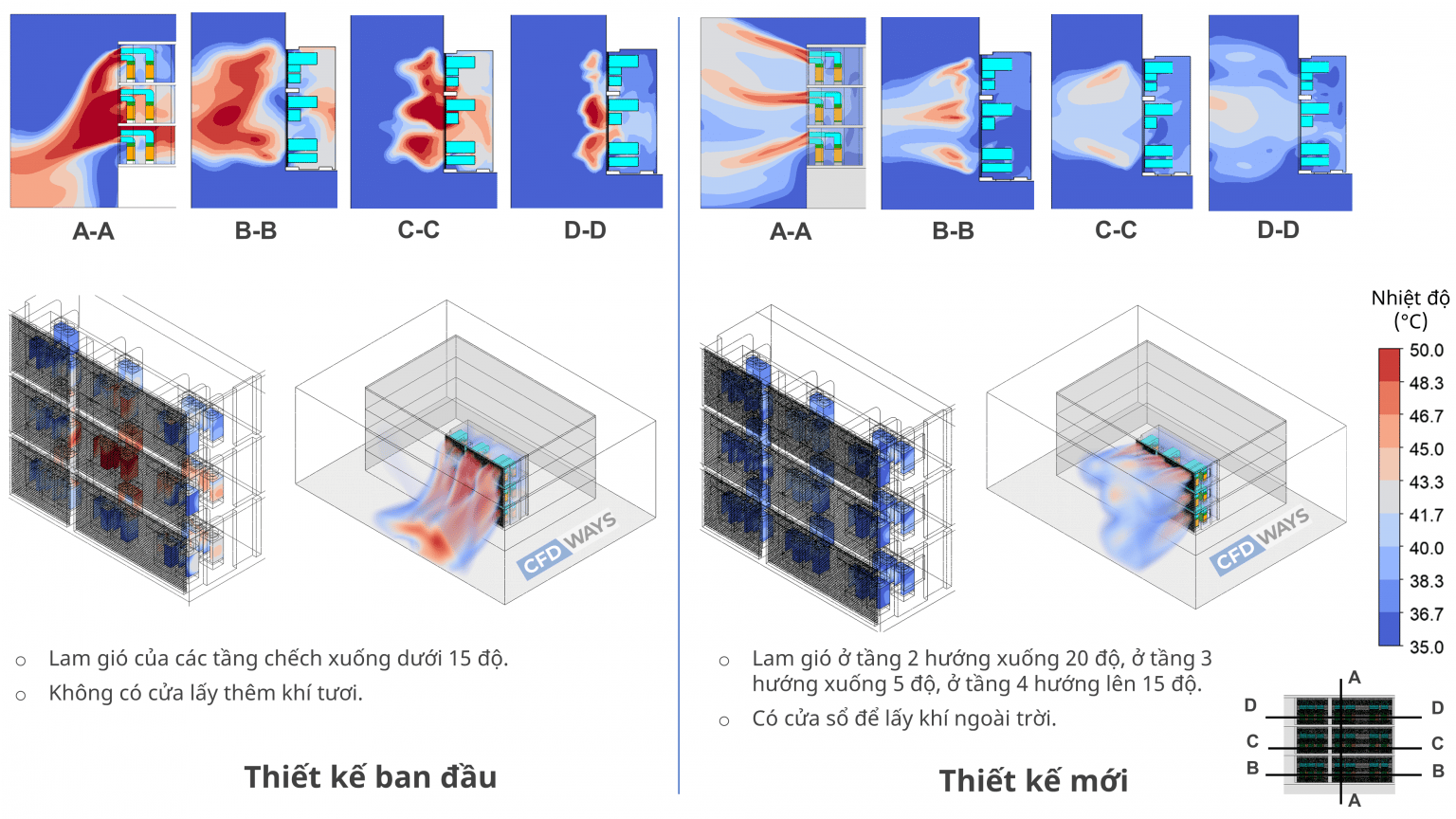
Temperature distribution around the condenser units
The upper panel of the chart below shows that in the original design 7 condensers run above the normal operating band (43 °C to 49 °C), where air conditioning performance falls markedly (<90%). In the new design every condenser is back inside the normal band (performance >95%). Using ducts and vanes to steer the flow does raise system resistance, so the air flow into the condensers drops. The lower panel shows the flow falling to 86–95% — still within the permitted range (>75%, with cooling capacity still above 90%). CFD therefore shows the new design is better than the original.
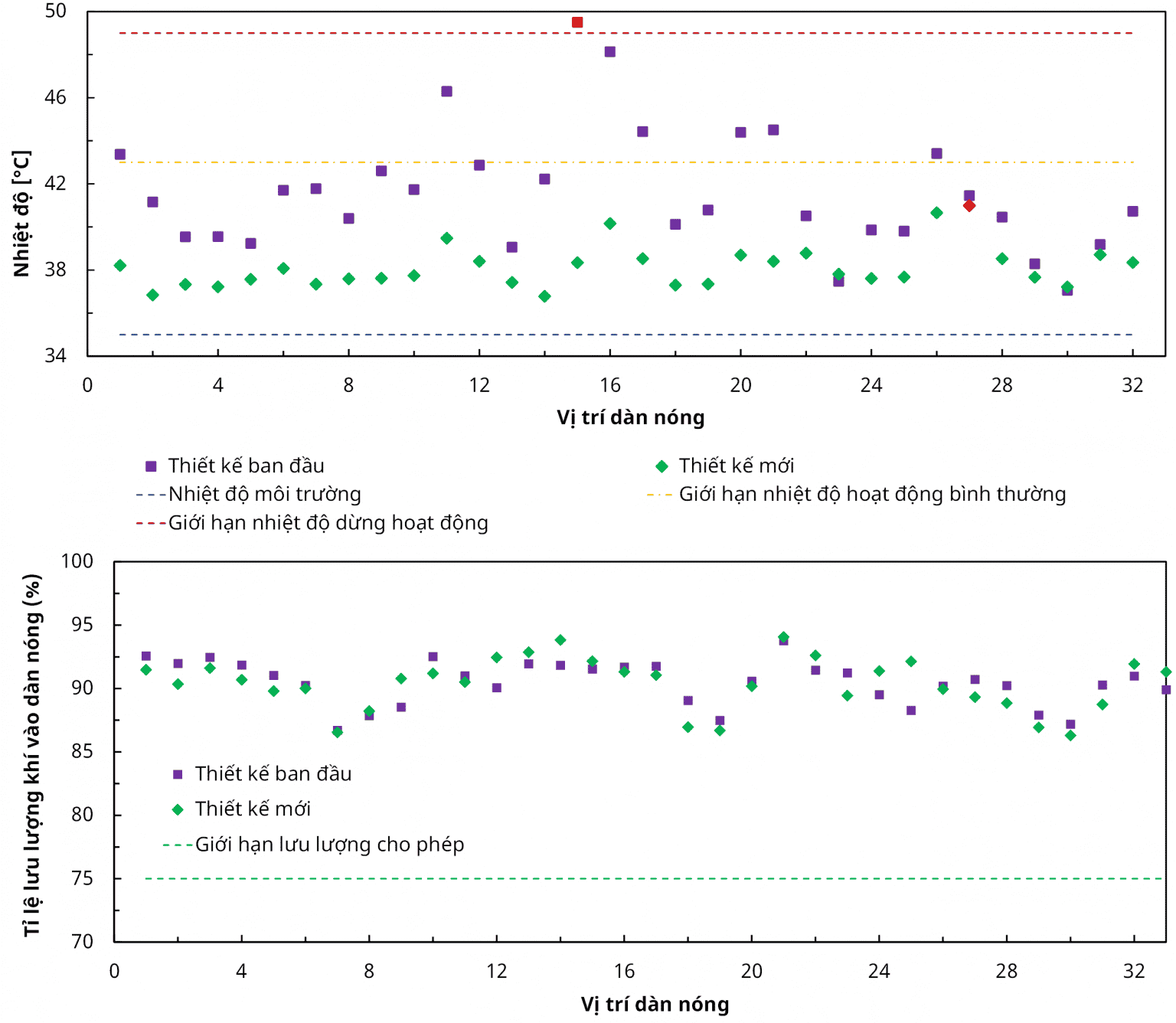
Intake temperature and air flow ratio for each condenser unit
Conclusion
Laying out and installing the condenser units of an air conditioning system looks simple, yet in practice it runs into problems that cut performance, cause shutdowns or even damage the machines. A 1 °C rise in ambient temperature costs 2–3% of performance, and as the temperature keeps rising one of the following happens:
- Cooling capacity falls but stays within limits, and more electricity is consumed to keep people comfortable (it takes longer to reach the set temperature).
- Cooling capacity falls beyond the permitted limit, so the comfort requirement cannot be met at all (the set temperature is never reached).
- The system shuts down once the temperature leaves the operating window.
- The system is damaged if it keeps running at high temperature.
Validating and optimizing the condenser layout becomes far simpler with CFD. Designers and installers get a fast, visual picture of the surrounding temperature and the air flow at every condenser, right at the design stage, and can propose improvements that keep the system at its highest efficiency. An optimal layout also saves electricity, cutting net emissions and contributing to the COP26 goals.