IndustriesEnvironmental engineering
Group 1 · Energy & Utilities

Environmental engineering

From chemical mixing tanks in water treatment to post-combustion flue-gas systems — where flow distribution and residence time decide the efficiency.

SNCR
NOx removal, waste incinerators
FGD
dry & wet SOx removal
RTD
residence-time analysis
30 MW
scale already delivered

Common problems

  • Dead zones in the tank — the chemical does not make enough contact and treatment falls below design
  • Skewed gas flow ahead of the treatment unit — part of the cross-section is overloaded while the rest sits idle
  • Injection outside the temperature window — with SNCR, a temperature offset lets ammonia slip through unreacted
  • Local fouling and erosion — unplanned shutdowns for cleaning and repair

Why simulation is needed

This equipment is large, enclosed and runs continuously: its interior cannot be observed directly, and it cannot be stopped for experiments. Measurements at a few discrete points cannot establish the actual flow pattern.

Simulation reconstructs the whole flow, temperature and concentration field, so several retrofit options can be compared before investing in fabrication.
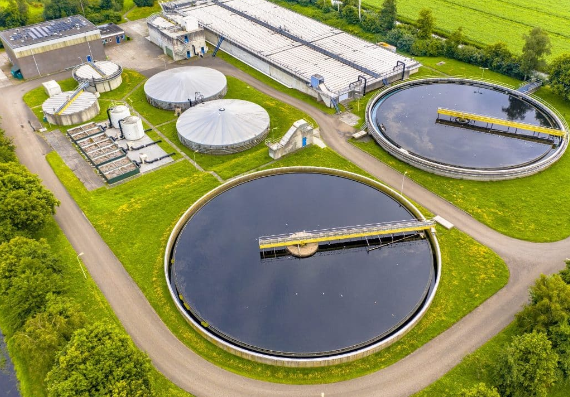
Simulation of flue-gas treatment equipment in environmental engineering
/image/nganh-moi-truong.jpg4:3 ratio (landscape)
Flow field inside a flue-gas treatment unit — the basis for choosing injector positions.

Equipment & processes we handle

Wastewater treatment

Mixing and contact tanks (RTD analysis, dead-zone detection), settling tanks, bioreactors.

Flue-gas treatment

SOx removal with dry and wet FGD, NOx removal with SNCR and ozone, dust filters.

Waste-to-energy

Grate combustion chambers, temperature distribution, burnout and emissions control.

Simulation methods

  • Single-phase and multiphase turbulent flow, with residence-time distribution (RTD) analysis
  • Lagrangian droplet and particle tracking for urea, ammonia and lime slurry injectors
  • Chemical reactions with emission models, coupled to the temperature field
  • Conjugate heat transfer for equipment walls and heat-exposed zones

What you receive

  • An engineering report with flow, temperature and concentration fields at the important sections
  • A quantitative comparison between the current state and each retrofit option
  • Specific recommendations: injector positions, flow-guide plates, dimensional changes
  • Model files handed over so your team can re-run them when needed

How we work

Collect the data

Drawings, operating parameters, field measurements.

Build & calibrate the model

Checked against field measurements before the results are used.

Test the options

Several retrofit options run in parallel and compared quantitatively.

Hand over & follow up

Report, recommendations and support during implementation.

Projects delivered in this industry

SNCR for a 30 MW waste-to-energy plant

Optimizing injector positions and layout within the reaction temperature window.

See the case study →

Desulfurization system

Flow distribution and phase contact inside a SOx removal unit.

See the case study →

Capabilities by equipment

The full list of equipment and processes CFDWAYS can handle.

See the capabilities →

Is your treatment equipment running below design?

Send the drawings and operating parameters — CFDWAYS will make a preliminary assessment of what simulation can reveal.

Send project details

Other industries: Chemical engineering · Energy, oil & gas · HVAC & building design