Solutions
Solutions

Simulation capabilities by equipment & process

Simulation is valuable only when the model reflects the real physics of the equipment. All eight equipment families below have been analyzed directly by CFDWAYS in projects since 2019.

01 · Flue-gas treatment

SOx removal — dry and wet FGD

Low removal efficiency despite more sorbent; pressure loss above design overloading the ID fan; uneven flow into the dust filter causing local wear.
  • Modeling: multiphase gas–solid flow (Lagrangian) + multi-species + turbulence; sorbent residence-time distribution; validated against design and operating data.
  • Delivered: a map of recirculation zones and bottlenecks; pressure loss per section; a flow distribution scheme with before/after KPIs.
  • Proven in the field: the client confirmed the model predicted pressure to within ~5% — reliable enough to size the ID fan.

Case study: dry FGD at a thermal power plant, 2022 →

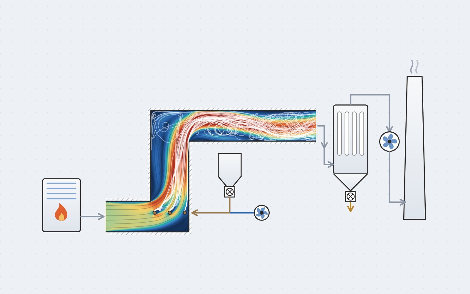
Geometry model and flow field of a dry desulfurization system
image/thiet-bi-fgd-01.jpg4:3 ratio (landscape)
From equipment model to flow field — dry FGD system, 2022 project.
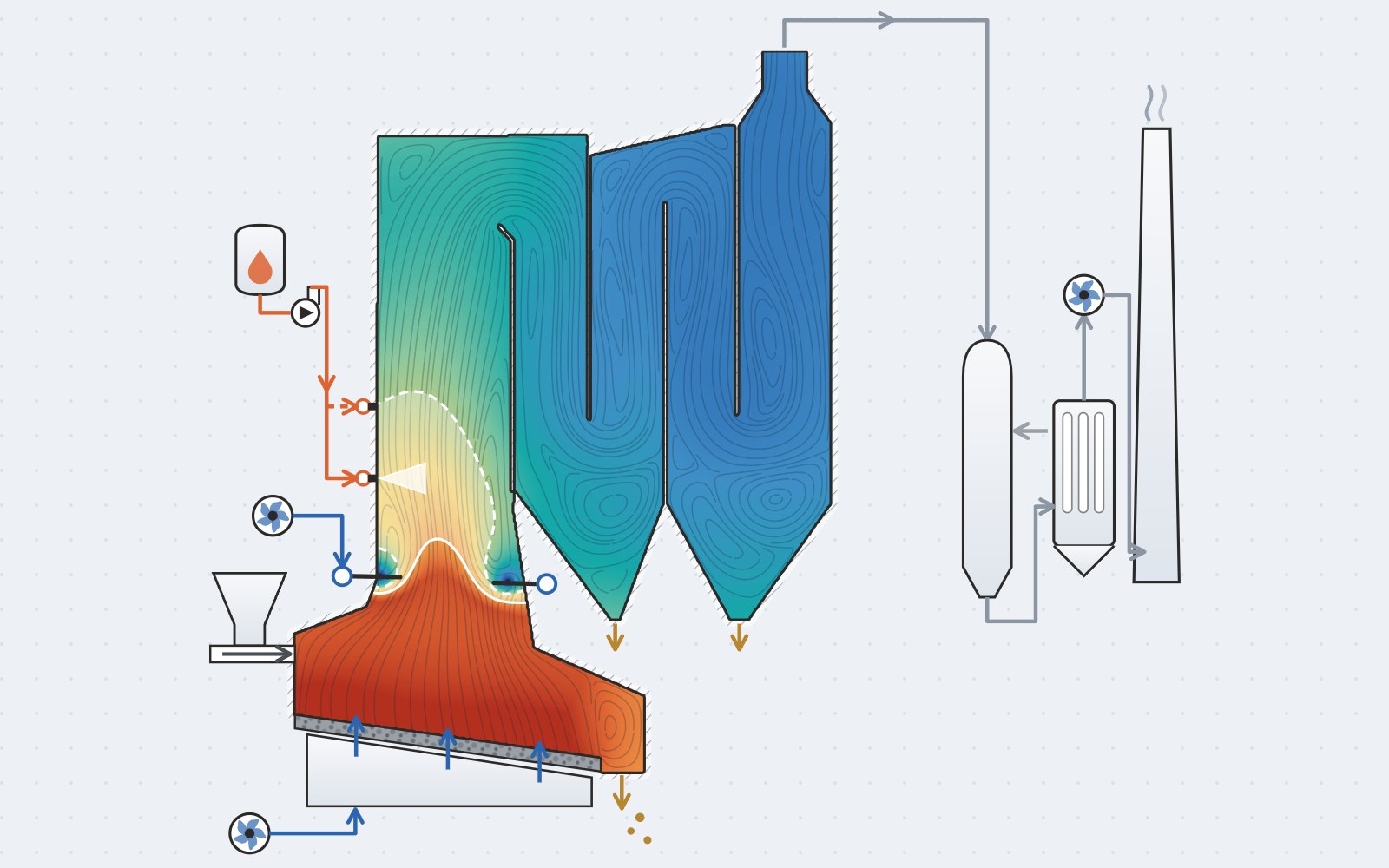
Flow, temperature and NOx concentration analysis inside an incinerator
image/thiet-bi-sncr-01.jpg4:3 ratio (landscape)
Recirculation, temperature field and NOx distribution — the basis for choosing the injection layout.
02 · Flue-gas treatment

NOx removal — SNCR and ozone DeNOx

Injector position and layout decide the removal efficiency, yet can only be judged after installation — and correcting a mistake on site is expensive.

  • Modeling: urea decomposition and NOx removal reactions; droplet evaporation; particle tracking for residence time; the 870–1100°C SNCR window inside a real combustion chamber.
  • Ozone systems in wet scrubbers: the cooling water spray and the ozone injection point optimized together to secure mixing, residence time and the right temperature zone.
  • Delivered: the injection layouts assessed against KPIs; the layout settled before installation.

Case study: 30 MW waste-to-energy plant →

03 · Combustion

Combustion chambers, industrial furnaces & alternative fuels

Flame stability and emissions when the fuel changes or the burner is retrofitted; assessing co-firing schemes for lower emissions before investing.
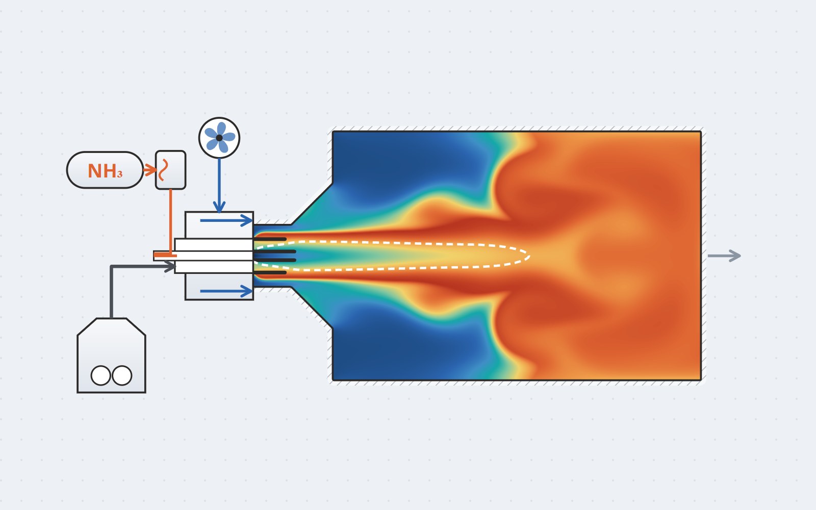
  • Modeling: multi-species reacting flow; swirl number and central recirculation zone analysis; compartment models (CSTR networks) to sweep many fuel scenarios quickly.
  • Delivered projects: coal gasification and fluidized-bed firing at brick plants (2023–2025); a cement plant calciner (2025); a fired heater (2025); a pyrolysis furnace producing charcoal (2021).
  • Gas path & fan selection: flue-gas duct design and fan selection based on segment-by-segment pressure loss — a charcoal pyrolysis plant (2025).
  • R&D in progress: NH₃ co-firing for thermal power plants (with Industrial University of Ho Chi Minh City) — first results: a co-firing ratio below ~20% keeps NOx controllable while still cutting CO₂; publication in preparation.
Flame characteristics for NH3 co-firing scenarios and swirl structure in the combustion chamber
image/thiet-bi-buong-dot-01.jpg4:3 ratio (landscape)
Flame characteristics for NH₃ co-firing scenarios and the swirl structure in a pulverized-coal combustor — CFDWAYS × IUH research.
04 · Heat recovery

HRSG, condensers, waste-heat boilers

Uneven flow through the finned tube bank reduces heat transfer and tube life; dead zones and bypass flow cause local corrosion and fouling; liquid–vapor distribution differs strongly between tubes.
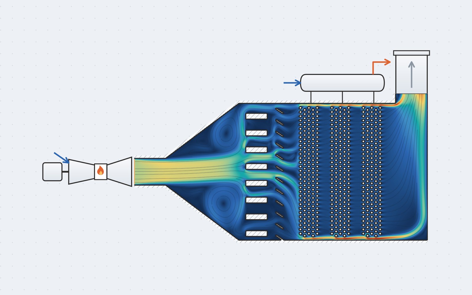
Pressure, temperature and velocity fields inside an HRSG
image/thiet-bi-hrsg-01.jpg2:1 ratio (landscape)
Pressure – temperature – velocity streamlines in an HRSG: locating flow skew ahead of the finned tube bank (2025 project).

Porous-medium approach

The finned tube bank modeled with Darcy–Forchheimer coefficients derived from a detailed tube-bundle simulation — balancing accuracy against computing cost.

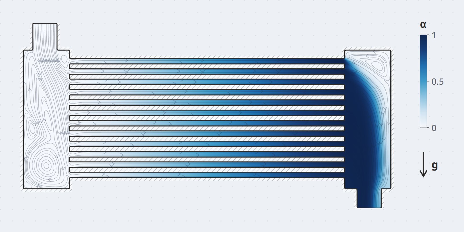
Multiphase evaporation–condensation

Quantifying how far each tube row deviates from the design flow; identifying dead zones, bypass flow and the risk of local corrosion inside the condenser.

Thermal stress coupling

Soft coupling to Simcenter 3D for thermal stress and fatigue; particle erosion models to assess tube life.
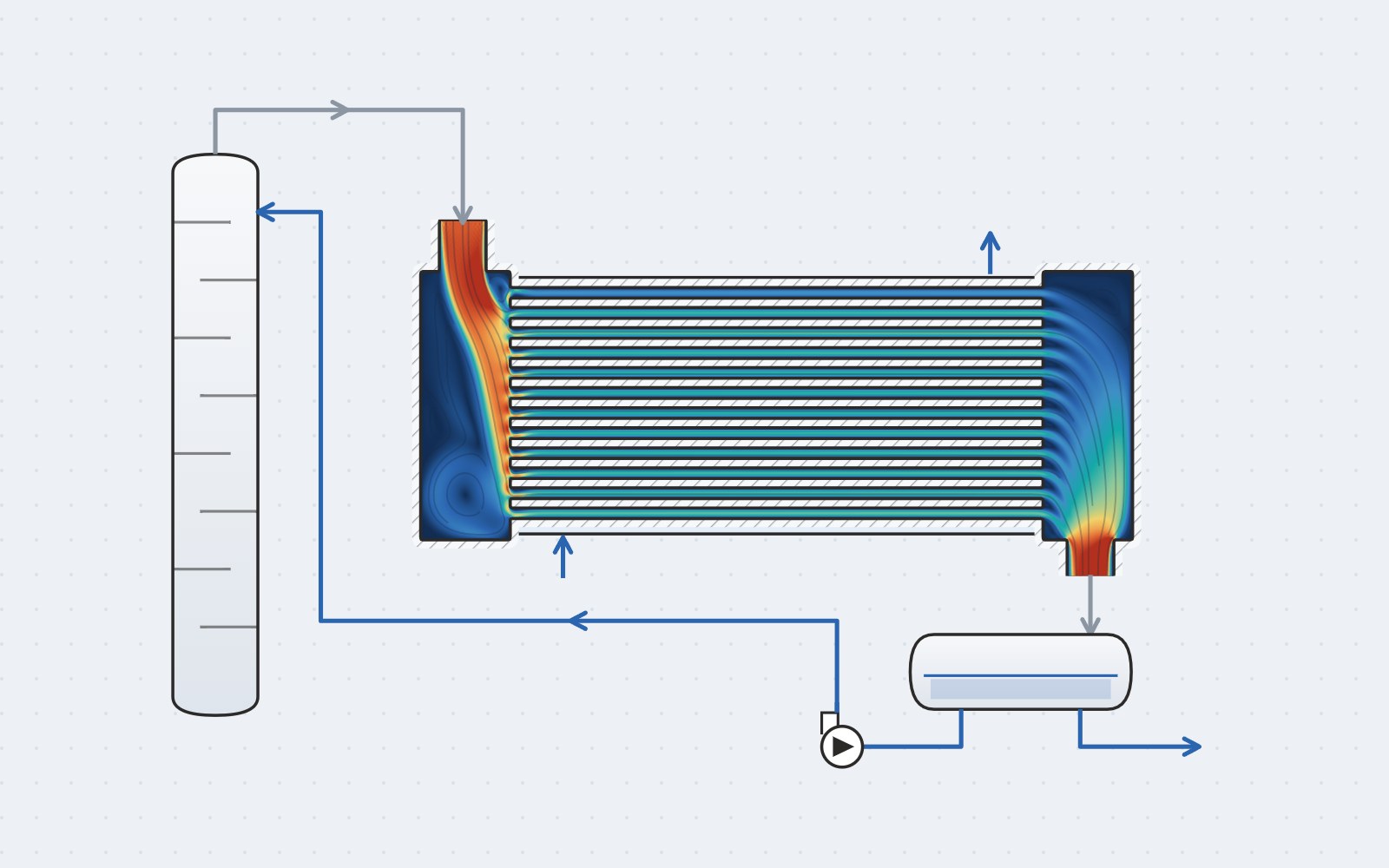
Flow distribution at the header and the heat-exchange tubes
image/thiet-bi-binh-ngung-01.jpg2:1 ratio (landscape)
Flow distribution at the header and tube bundle — maldistribution diagnosis.
Liquid phase distribution inside the condenser
image/thiet-bi-binh-ngung-02.jpg2:1 ratio (landscape)
Liquid phase distribution (VOF) in a shell-and-tube condenser.
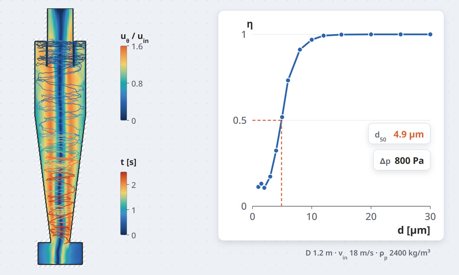
Particle residence time and cyclone design indices
image/thiet-bi-cyclone-01.jpg5:3 ratio (landscape)
Particle residence time and cyclone design indices — the basis for the design tool CFDWAYS developed and handed over to the client.
05 · Particle equipment

Spray dryers, cyclones & dust filtration

High energy cost from a sub-optimal design; cyclones with high pressure loss, poor separation and uneven wear; dust filters fed by a skewed inlet flow.

  • How we work: energy audit → CFD to locate the bottleneck → improvement plan → a KPI set for continuous tracking.
  • Accompanying tools: reusable cyclone design software; a digital twin platform monitoring the drying system's energy use.
  • Results in the ceramic tile industry: payback under 2 years, 5–10% heat and 10–20% fan power saved.
  • Dust filtration & particle recovery: electrostatic precipitator (R.EP pilot at La Hien cement plant, 2024), baghouse (2024), dust collection system (2024) — the same gas–particle model class as cyclones.
  • Other dryer types: piping and flow distribution for a freeze dryer (2023).

Case study: spray dryer at a tile plant, 2022–2024 →

06 · Separation & mixing

Separation & mixing equipment

Three-phase separators with dead zones and liquid carry-over in the gas stream; mixing and chemical contact tanks whose residence time is far from the nominal value.
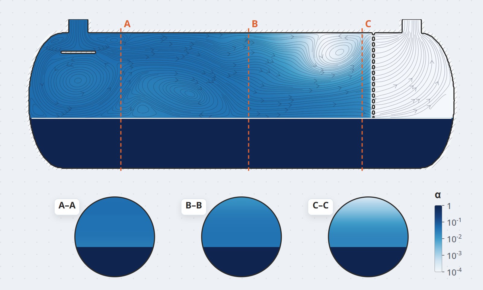
  • Modeling: multiphase VOF/Eulerian; residence-time distribution (RTD); phase separation and carry-over phenomena.
  • Academic foundation: bubble column hydrodynamics models published in Chemical Engineering Journal, AIChE Journal and Fuel, used directly in industrial projects.
  • Industrial project: environmental treatment system TP1 (United States, 2025) — CFD analysis and design improvement.
  • Extensions of the same model class: three-phase separators (oil & gas), PAC mixing and contact tanks (water treatment).
Phase volume fraction distribution in a separator
image/thiet-bi-phan-tach-01.jpg5:3 ratio (landscape)
Phase volume fraction across sections of a separator.
07 · Buildings

HVAC & building environment

Thermal comfort, indoor air quality, industrial ventilation, car park smoke control, condenser unit placement, industrial freezing cabinets and cold rooms, wind loading and wind tunnels.

Six technical blog articles from the CFDWAYS team go deeper into this group of problems.
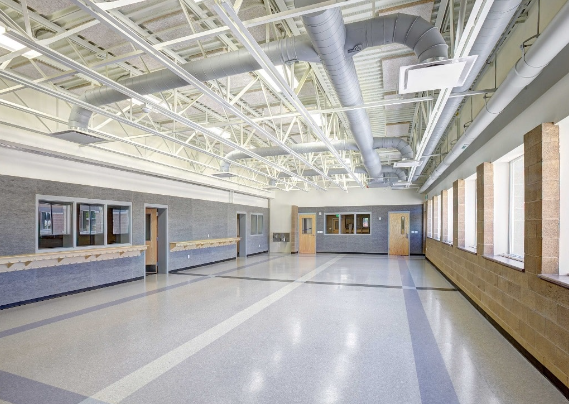
HVAC & building design industry page →

HVAC and building design
image/nganh-hvac.jpg~2:1 ratio (landscape)
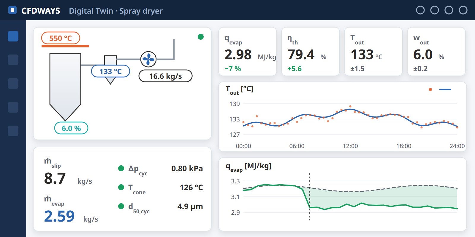
The energy monitoring digital twin platform developed by CFDWAYS
image/cong-cu-digital-twin.jpg2:1 ratio (landscape)
The digital twin platform monitoring a spray-drying system — developed by CFDWAYS.
08 · Operations

Digital twins & custom engineering tools

A one-off simulation answers one question; daily operation needs a tool that keeps answering.

  • Digital twins that work in operation: virtual sensors, reduced-order models (ROM), model predictive control (MPC), predictive maintenance — all on top of a validated physical model.
  • Client-specific tools: Excel/VBA and Python integration with STAR-CCM+; delivered together with training on how to use them.

Tools: Simcenter STAR-CCM+ · Simcenter 3D · Amesim · FloEFD/FloTherm · FloMaster · HEEDS · gPROMS · Cantera · MATLAB/Simulink

Other equipment? Send a description

If your problem belongs to the same class of physics — flow, heat transfer, reaction, multiphase — send us a description. CFDWAYS will reply with a suitable approach for your equipment.

Send your problem description