ProjectsHRSG, thermal power plant
Case study · Thermal power · Belgium · 2025

Full gas-path flow analysis of an HRSG — finned tube bank, silencer and damper

Full path
turbine outlet to stack in one model
Porous medium
finned tube bank built on Darcy–Forchheimer
2 model levels
detailed sample bundle → porous coefficients for the full bank
3 KPI groups
flow uniformity · pressure loss · heat transfer

Context & problem

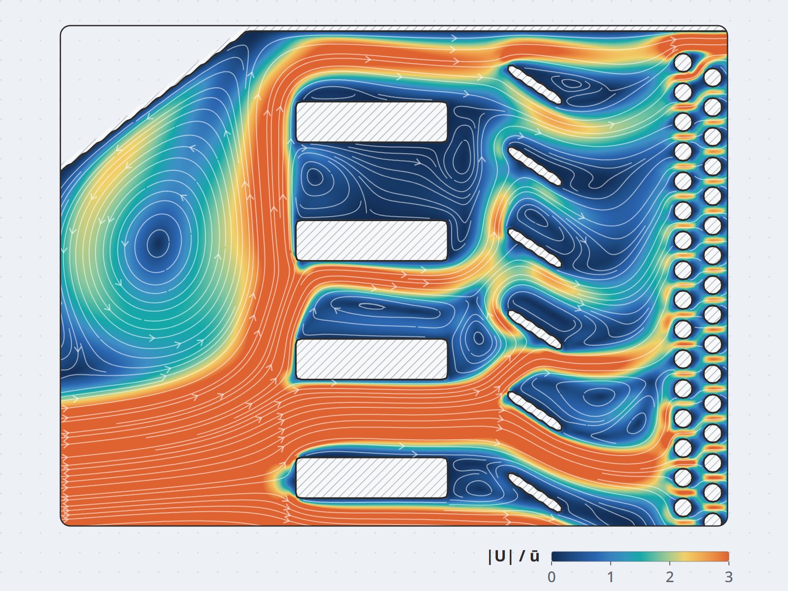
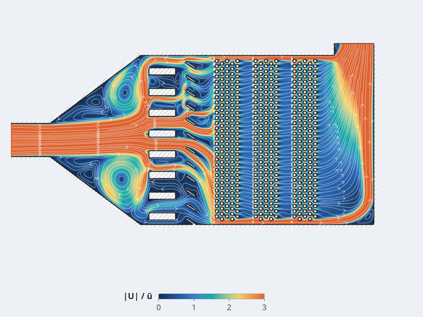
Hot gas leaving the turbine passes through the diffuser duct, the silencer and the damper before it reaches the HRSG finned tube bank. Every component on the way bends and squeezes the flow, so the flow arriving at the tube rows is rarely as uniform as the design assumed: part of the bank takes far too much flow while the rest works below capacity.

The consequence is twofold — the heat transfer efficiency of the whole block falls below design, and at the same time dead zones and bypass flow cause fouling, local corrosion and shorter tube life. Modeling thousands of finned tubes in detail is far beyond the computing budget of an engineering project.

Approach

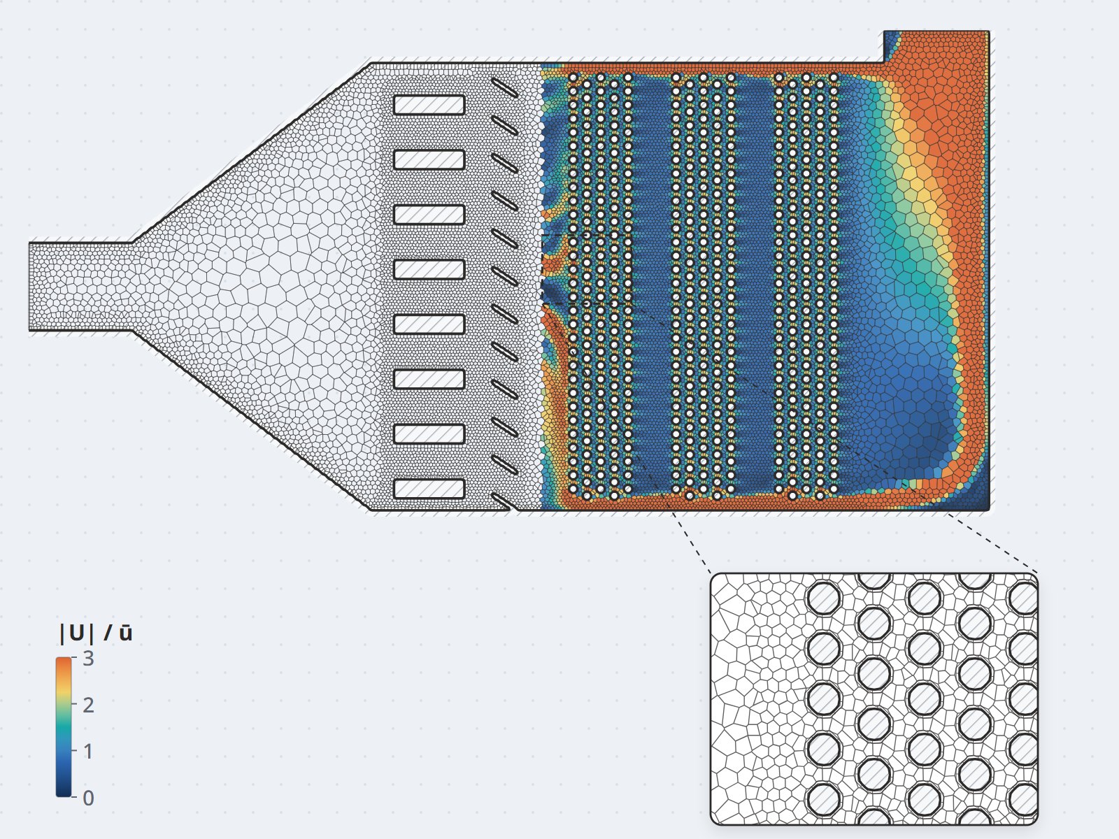
  • A two-level model: a detailed simulation of one sample tube bundle to extract the Darcy–Forchheimer resistance coefficients, then applying those coefficients to the full bank as a porous medium — keeping the real resistance behavior while the computing cost stays within the project.
  • A continuous scope: the diffuser duct, silencer and damper sit in the same model as the tube bank, because they create the flow skew; a narrower scope would require assuming the inlet boundary condition.
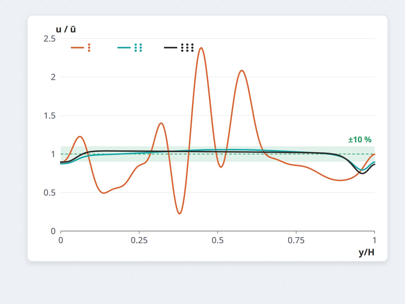
  • A quantitative KPI set: velocity uniformity on the section ahead of the tube bank, pressure loss per section and flow distribution.
  • Validation: pressure loss and operating conditions checked against the design data before the model was used to compare options.

Results

  • The location and the cause of the flow skew along the gas path were identified — clearly separating what comes from the diffuser geometry and what comes from the silencer and damper.
  • The KPI set allows flow-correction options to be ranked on a single common measure rather than debated qualitatively.
  • The calibrated porous-medium model is reusable for other load cases and damper configurations — each subsequent analysis costs far less than the first.

Value

With an HRSG, most of the cost lies in shutting the plant down for repairs. A full gas-path model allows the decision on modifying the diffuser duct to rest on a KPI comparison, made before the maintenance window rather than after dismantling.
Project gallery

HRSG, thermal power plant project photo 1
/image/thiet-bi-hrsg-02.jpg4:3 ratio (landscape)
HRSG, thermal power plant project photo 2
/image/thiet-bi-hrsg-03.jpg4:3 ratio (landscape)
HRSG, thermal power plant project photo 3
/image/thiet-bi-hrsg-04.jpg4:3 ratio (landscape)
HRSG, thermal power plant project photo 4
/image/thiet-bi-hrsg-05.jpg4:3 ratio (landscape)

Is your tube bank performing as designed?

Send the gas-path schematic and operating conditions — CFDWAYS will advise on the extent to which flow distribution and pressure loss can be quantified by simulation.

Send project details

Related projects: Refinery overhead condenser · HRSG, condenser & waste-heat boiler capabilities · Simcenter STAR-CCM+