ProjectsOzone DeNOx
Case study · Environment · South Korea · 2025

Optimizing an ozone DeNOx system in a wet scrubber

2 injection systems
cooling water and ozone optimized together
Droplet evaporation
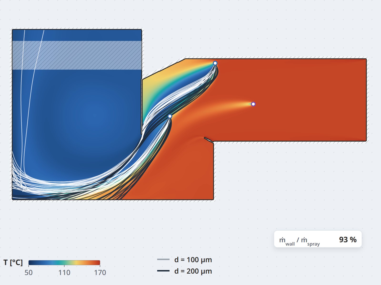
Lagrangian model for the cooling spray curtain
3 constraints
mixing · residence time · reaction temperature window
Before installation
layout settled on the model, no trial and error on site

Context & problem

Ozone oxidizes NO into higher, more soluble NOx forms so the wet scrubber downstream can absorb them. That reaction only works in a certain temperature range: if the gas is too hot the ozone decomposes before it can react, so a cooling water spray curtain has to sit ahead of the ozone injection point.

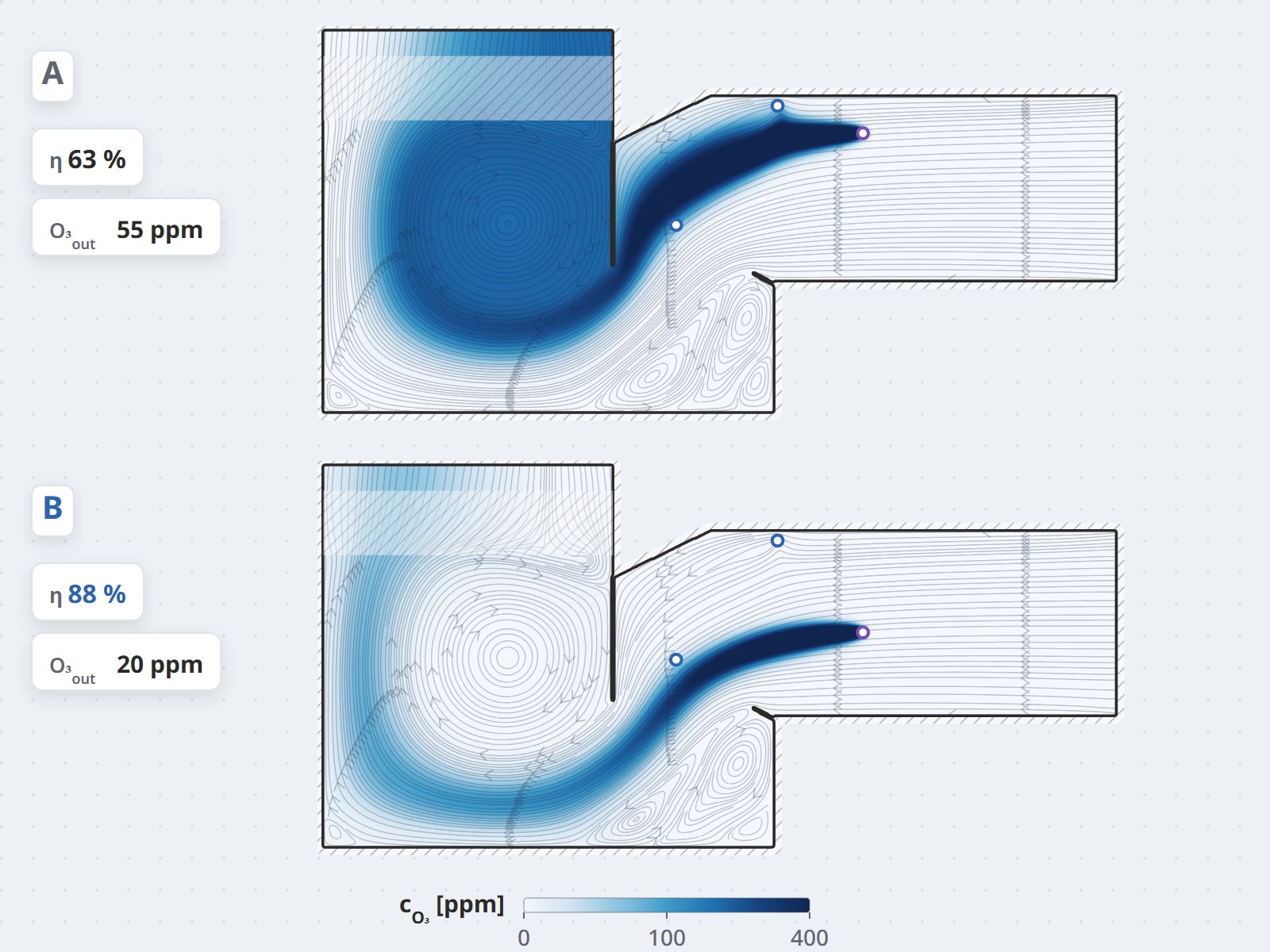
The two injection systems therefore constrain each other. Spray too close and the ozone meets droplets that have not fully evaporated; too far away and the gas has not cooled enough. On top of that, the ozone has to mix evenly and have sufficient residence time before entering the scrubber — three requirements pulling the injector position in three different directions.

Approach

  • Optimizing both injection systems together rather than one after the other: the cooling spray curtain and the ozone injection point were studied as a single configuration, because the result of the first is the inlet condition of the second.
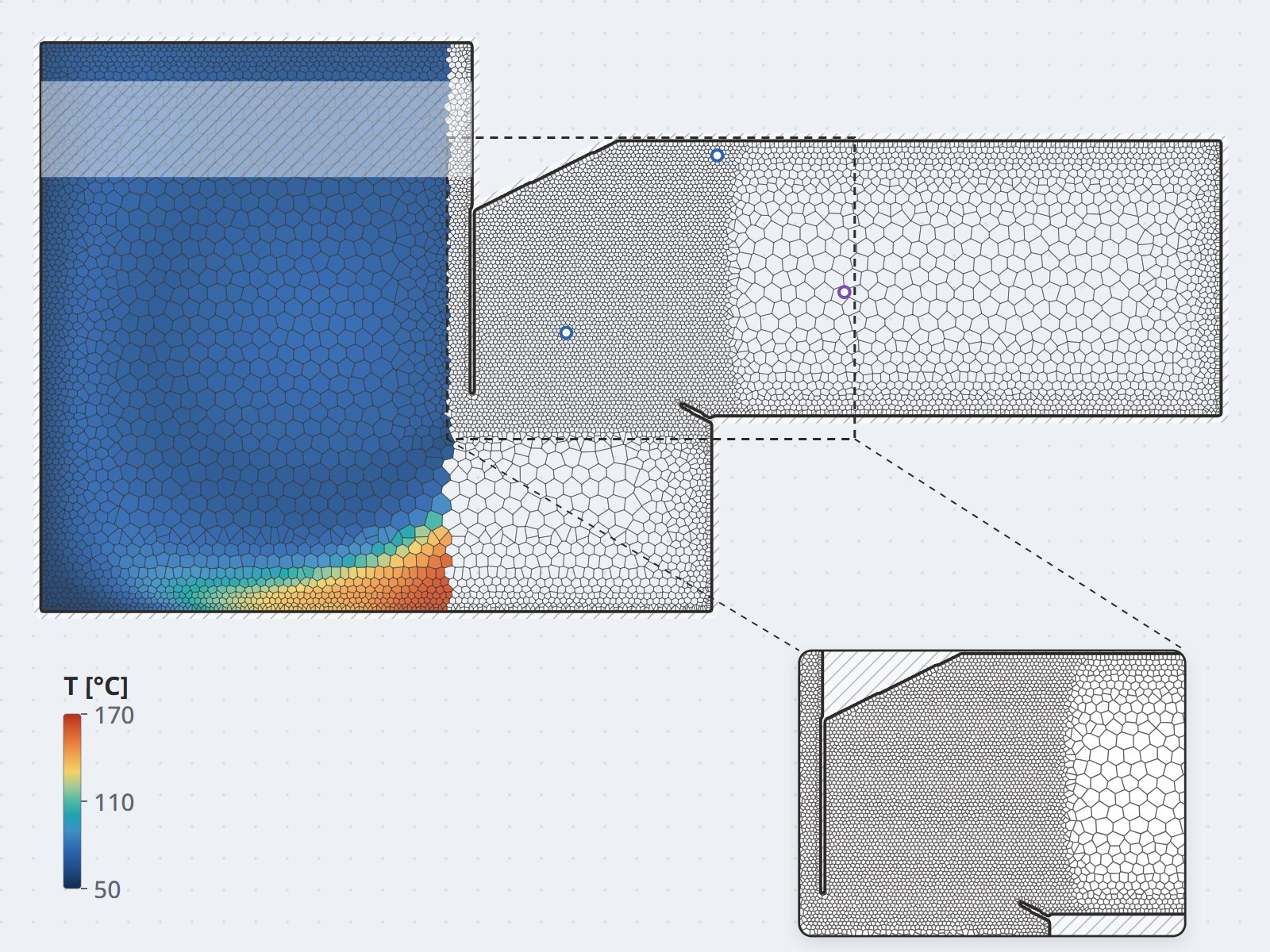
  • Lagrangian droplet evaporation for the water spray — establishing the distance over which droplets fully evaporate and the actual gas temperature field at the ozone injection plane.
  • Three deciding indices: ozone concentration uniformity across the section, residence time up to the scrubber inlet, and the fraction of gas flow inside the reaction temperature window.
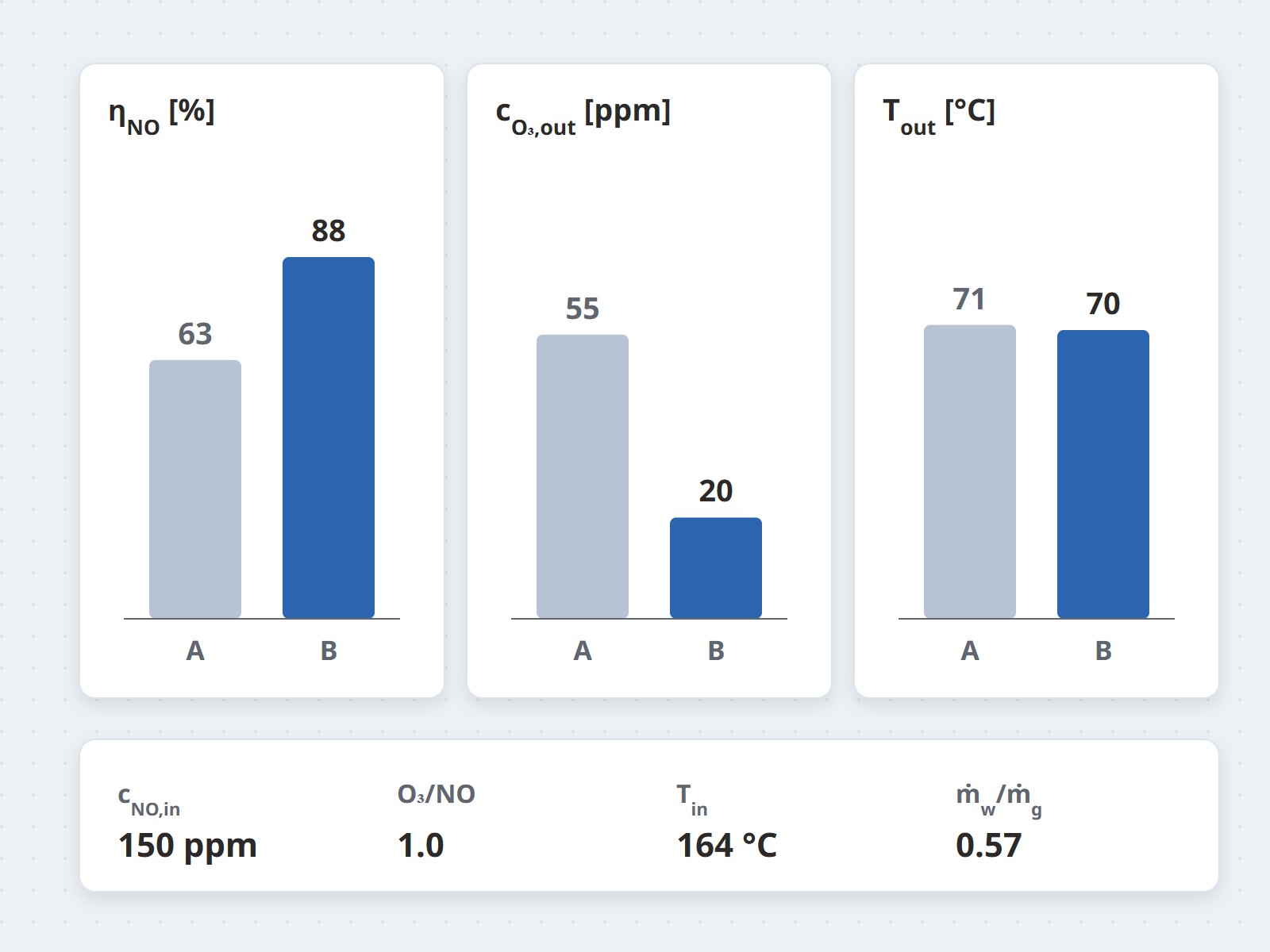
  • A configuration loop: nozzle count, elevation, injection direction and flow rate compared on the same set of indices to settle the layout before the injection rig was fabricated.

Results

  • The cooling water and ozone injection layouts were settled together, satisfying all three constraints of mixing, residence time and temperature window.
  • The on-site trial-and-error loop was eliminated: unsuitable options were eliminated on the model before any rig was welded.
  • The model was retained as an assessment tool for future changes in load or flue-gas composition.

Value

A flue-gas treatment system has to meet the emission limit while being constrained by the space available. Simulation allows every layout option to be tested within that tight space at the cost of computing time alone, avoiding the losses of an incorrect installation.
Project gallery

Ozone DeNOx project photo 1
/image/thiet-bi-denox-02.jpg4:3 ratio (landscape)
Ozone DeNOx project photo 2
/image/thiet-bi-denox-03.jpg4:3 ratio (landscape)
Ozone DeNOx project photo 3
/image/thiet-bi-denox-04.jpg4:3 ratio (landscape)
Ozone DeNOx project photo 4
/image/thiet-bi-denox-05.jpg4:3 ratio (landscape)

About to invest in NOx removal or upgrade a scrubber?

For removal efficiency, injector position matters more than equipment capacity. Send the gas-path schematic and operating conditions — CFDWAYS will respond with an assessment approach.

Send project details

Related projects: SNCR, 30 MW waste-to-energy plant · Dry flue-gas desulfurization · NOx removal capabilities