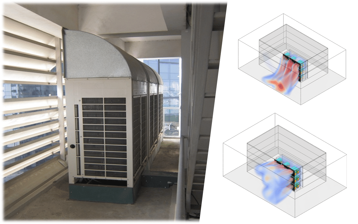

This article shows how CFD can predict, and then optimize, the performance of a workshop extract ventilation system. The system modeled comprises an industrial centrifugal extract fan with 8 blades, Ø0.57 m, drawing air from a 10×4×4 m room through five intake openings.
The workshop extract ventilation system [source]
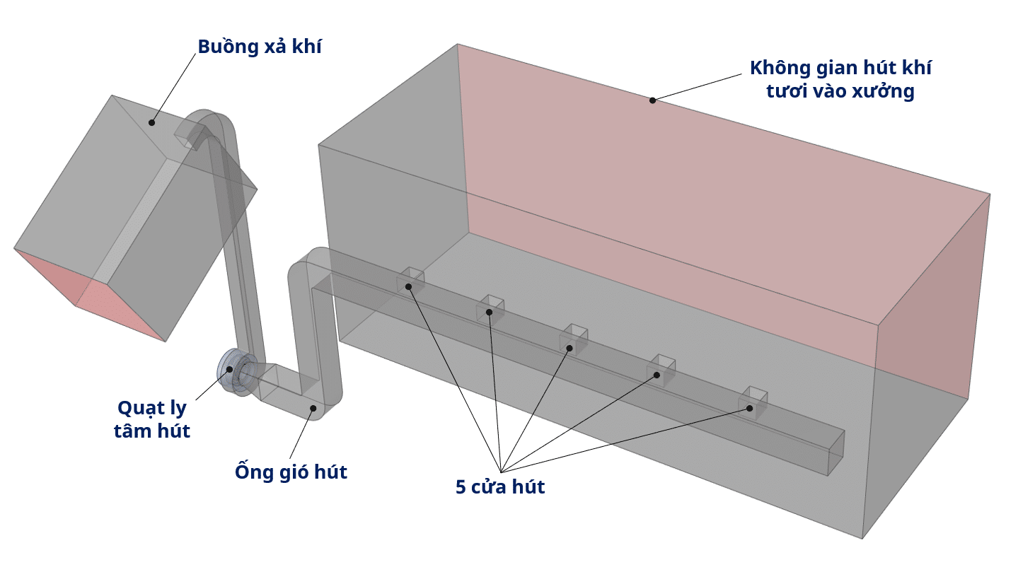
The extraction flow must be distributed evenly across the five intakes in the room. The aim is to remove any toxic vapors effectively while also reducing the locally high velocities (above 10 m/s) inside the ducts. The minimum flow requirement for the fan is 2.6 m3/s at 2500 rpm. The main goals of this project were to use CFD to (1) assess and optimize the flow distribution across the intakes, and (2) optimize the fan performance so it meets the required extraction flow.
The basic setup for the CFD analysis
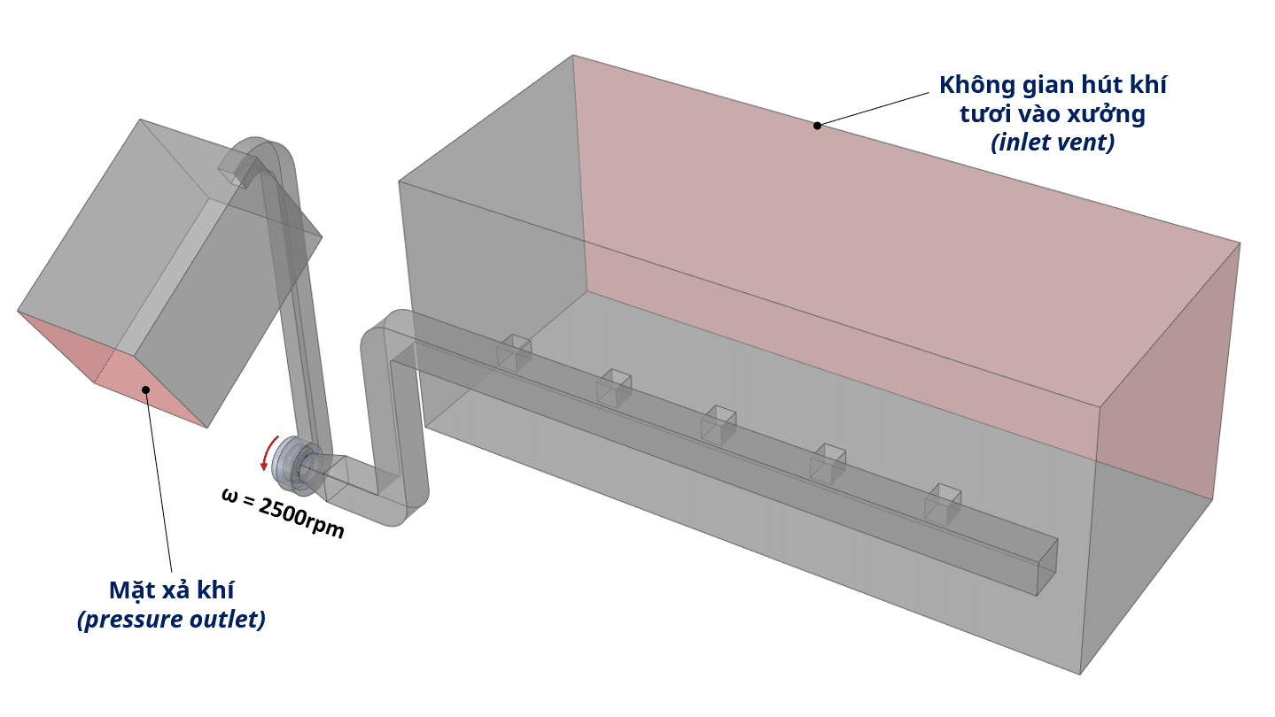
The CFD analysis was carried out on a 3D CAD model representing the air volume. The room-side intake surface and the discharge side of the outlet plenum (marked in red) are set as open to atmosphere (gauge pressure = 0). The impeller speed of the extract fan was set to 2500 rpm. The way a fan simulation is set up is described in this article.
Boundary condition setup for the CFD simulation
Analyzing the results of the original design
The model was meshed with ~1.2 million polyhedral cells; the simulation was stopped after about 4000 iterations, once the flow through the five intakes had stabilized.
Flow distribution across the five intakes, with a section showing the velocity field
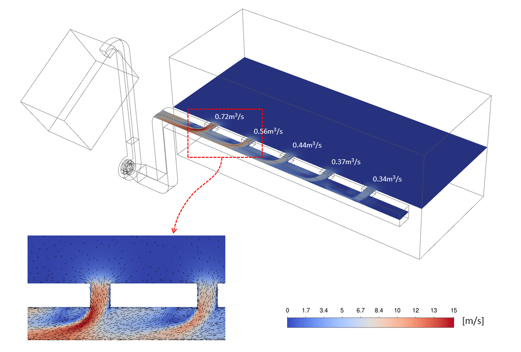
The figure above shows a section through the velocity field at the intakes, from which the volumetric flow through each one can be computed. The difference is considerable — from 0.72 m3/s at the far left intake to 0.34 m3/s at the far right. The velocity through the intake nearest the fan exceeds 10 m/s, showing that the original design does not meet the required operating conditions. The figure also reveals low-velocity regions in the main duct and recirculation zones where the flow tends to run back toward the intake — caused by the streams from each intake competing to exit through the main duct.
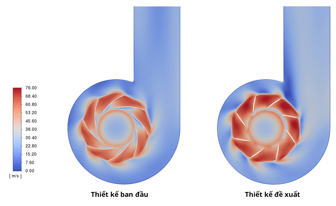
On the fan side, several low-velocity regions can be seen around the blade leading edges. This indicates flow separation caused by too large a change in incidence angle as the air passes along the blade. The greater the separation, the more the aerodynamic efficiency of the machine falls.
Velocity distribution through the fan blades (on a section perpendicular to the blade)
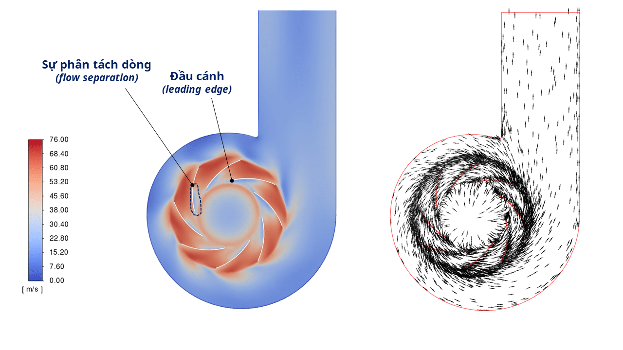
With the current design, the fan delivers a flow rate of 2.42 m3/s, below the design requirement. A new extraction system design was therefore proposed to distribute the air more evenly between the intakes and to bring the new fan up to the minimum required flow rate of 2.6 m3/s.
The improved ventilation system design proposed
The figure below shows the changes proposed to the extraction system. (1) A smoother change of direction, using curved ducts between each intake and the fan inlet. Every intake gets its own duct, all converging into a large manifold. This layout removes the recirculation and lets the streams run straight to the fan.
The optimized ductwork design proposed
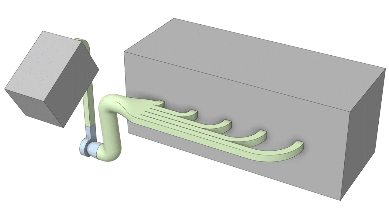
(2) For the fan, the blade attack angle is increased from 20° to 40° and the blade curvature is reduced to limit the flow separation seen in the original design.
The improved fan blade design proposed
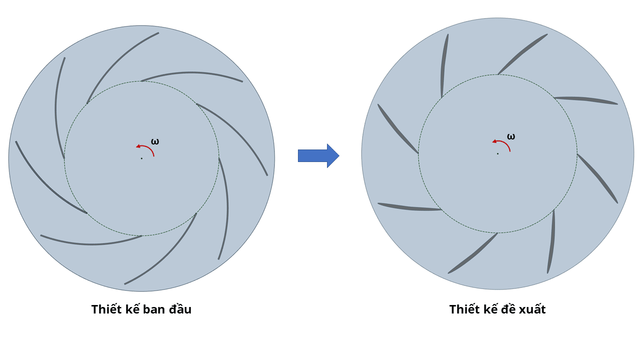
Comparison: original design vs proposed design
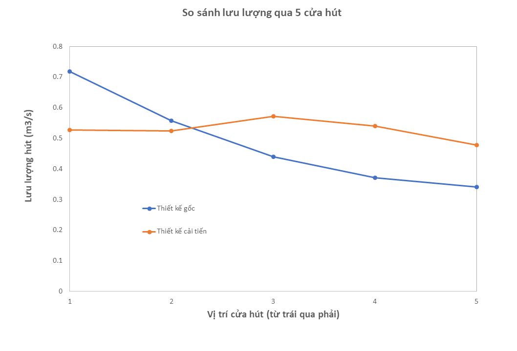
The simulation shows a marked improvement in the flow distribution across the intakes: the flow differs by at most 0.05 m3/s between intakes. The peak velocity also drops to about 9 m/s.
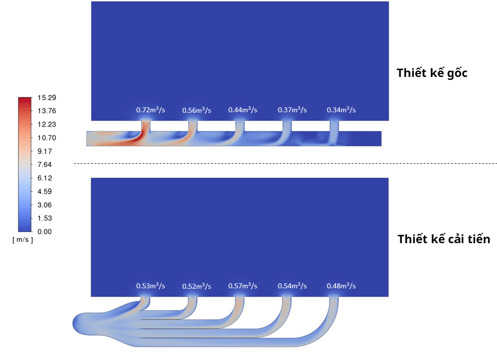
Velocity and flow distribution across the five intakes in the original and proposed designs
The air flow is distributed more evenly across the ducts, as the figure below shows more clearly:
Comparing the flow distribution across the intakes in the original and improved designs
The velocity field on a vertical section through the impeller shows clearly that the improved blade design produces higher velocities than the original and therefore a greater flow — 2.64 m3/s at the same impeller speed (2500 rpm). The flow separation around the blade leading edge present in the original design has also been removed.
Velocity distribution through the blades in the old design (left) and the new one (right)
Conclusion
In this project the design of a workshop ventilation system was assessed and optimized using CFD. The results showed that the extract fan delivered less flow than required. The intakes drew uneven flow, which created locally higher velocities than recommended, so the system would be prone to vibration and unwanted noise in operation. Problems like these make design improvements necessary.
The new design increases the attack angle and reduces the curvature of the fan blades, and redesigns the ducts between the intakes and the fan inlet. Comparing the new design with the original shows the new fan reaches 2.64 m3/s — above the minimum required 2.6 m3/s — and the locally high velocities in the ducts have been removed, with values now below 10 m/s.