Context & problem
The plant wants to raise the thermal substitution rate in the calciner. Besides 6 t/h of coal, the calciner
takes rice husk, solid waste, discarded footwear and liquid waste — about 27.5 t/h of alternative fuel, many
pieces up to 80 mm. Fuel this coarse burns out only where it meets enough temperature and O₂ for long enough;
if it is if it is fed at the wrong point, CO rises, unburnt fuel falls back into the kiln and the raw meal calcines less.
Approach
- A 3D model of the calciner from the kiln outlet (kiln gas at 1,150°C) to just before cyclone C5, with the
955°C tertiary-air duct from the cooler, raw meal from C4 (300 t/h at 800°C), the two coal points and the
alternative-fuel chutes.
- Multiphase model: gas with coal, rice husk, solid waste, footwear, liquid waste and raw-meal particles; fuel
combustion and CaCO₃ calcination kinetics from the published literature (Nakhaei 2018; Mikulčić 2012).
- Calibration against operation: temperature and calcination degree within 15% of the plant measurements, so
every option is compared with the current design on the same model.
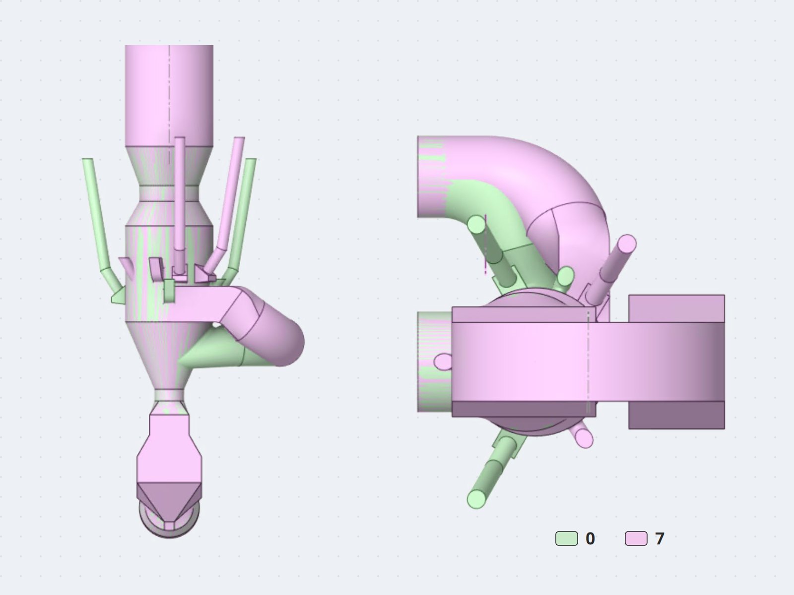
- Three rounds of options on one set of criteria (solid residence time, combustion efficiency, calcination
degree, CO, pressure drop, retrofit difficulty): 6 flow options, 2 chute relocations, and design 7 — a new
tertiary-air connection entering the chamber tangentially, cyclone-style, with the chutes rearranged at the
same elevation.
Results
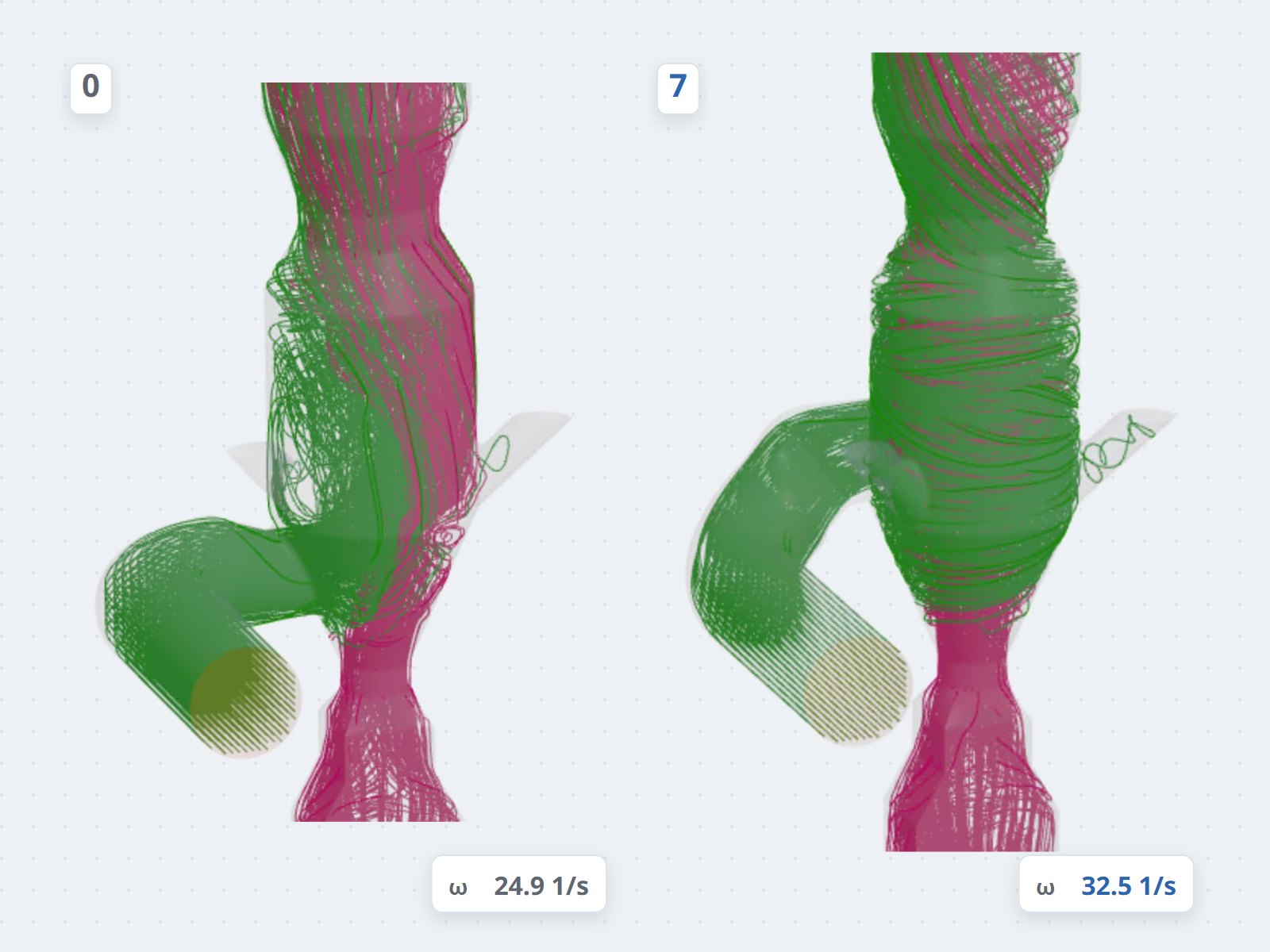
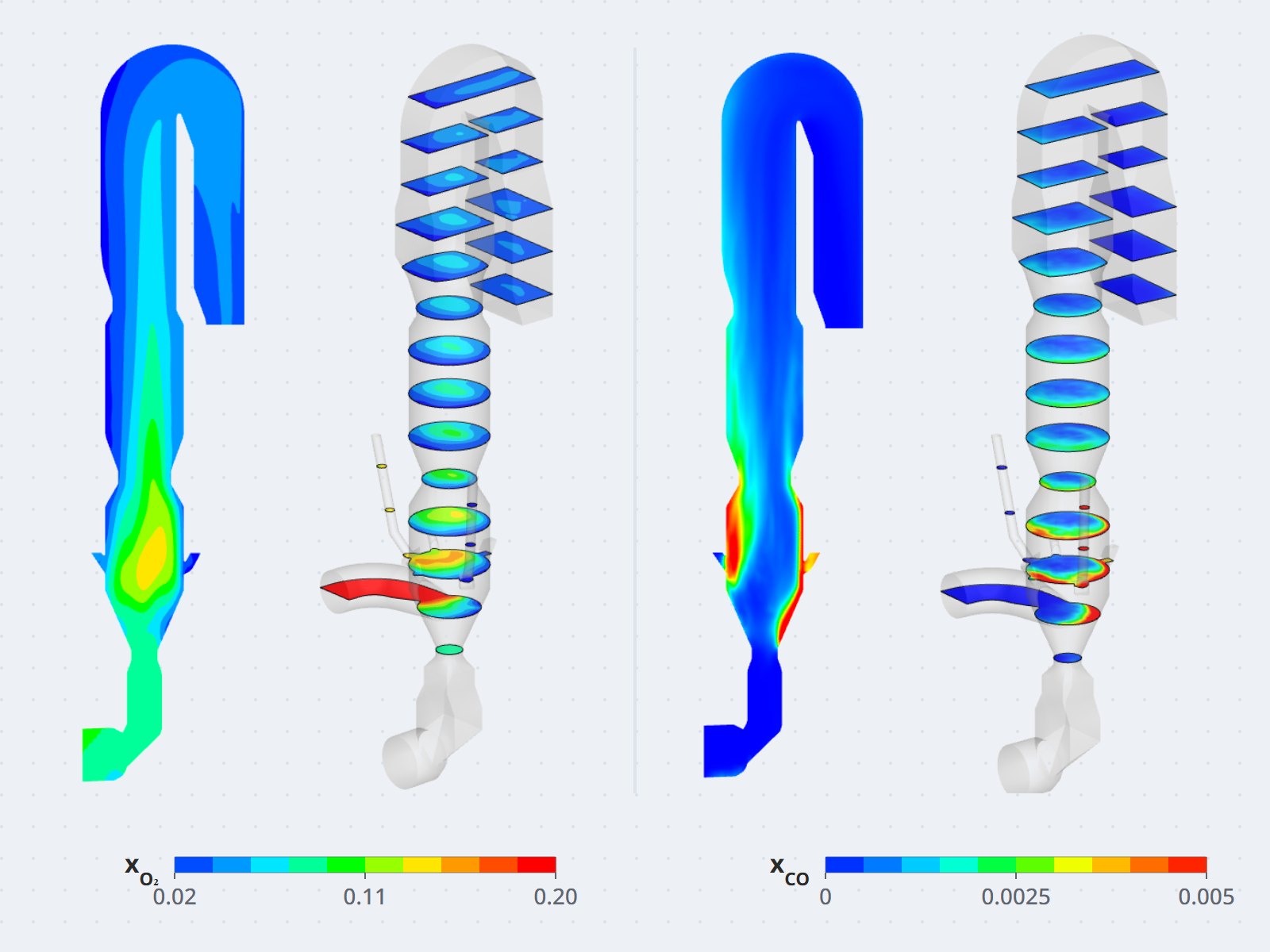
- Current design: a large dead zone above the tertiary-air inlet; kiln gas and tertiary air mix poorly, so O₂
stratifies and CO concentrates in the O₂-poor zones near the wall; 13.2% of the solids fall back into the
kiln riser.
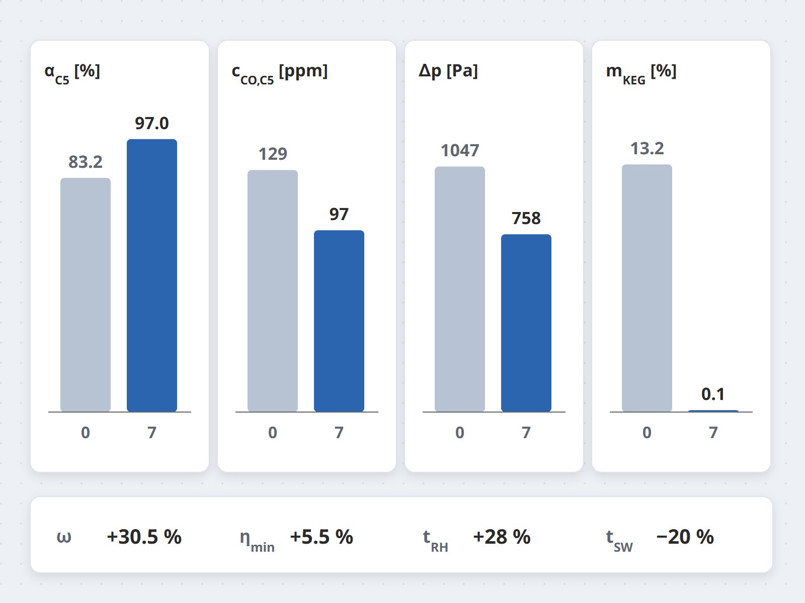
- Design 7, selected: chamber vorticity +30.5%, calcination degree at the C5 inlet +16.6%, CO
−24.9%, lowest combustion efficiency among the alternative fuels +5.5%, solids falling into the
kiln riser down to 0.1%, total pressure drop −27.6%.
- Residence time of coal, solid waste and footwear is 16–20% shorter (rice husk 28% longer), yet the better
mixing burns more fuel and calcines more meal than the current design.
Value
Lower CO at the same fuel input gives the plant room to raise the substitution rate while keeping CO at today's
operating level. The lower pressure drop can save up to 32% of the fan power for the calciner section, provided
the ID fan stays at its best-efficiency point.