Context & problem
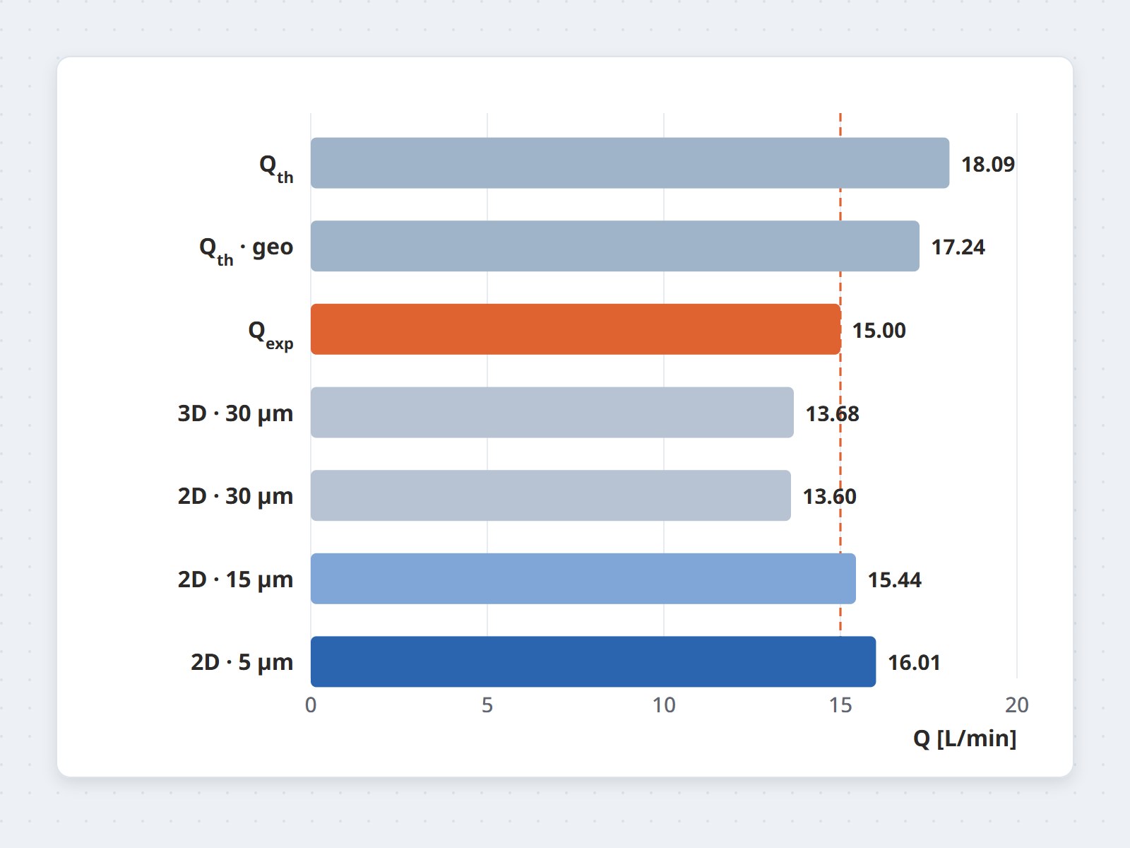
The Jet A-1 fuel gear pump, developed by a Vietnamese R&D organisation, delivered 15 L/min on its test rig
(21 atm, 6,000 rpm), clearly below the 18.09 L/min given by its geometry. The tip clearance to the casing is
only 30 µm, the gap between the teeth smaller still, and the pressure in the tooth spaces changes with every
mesh — quantities that are hard to measure directly. A trustworthy CFD model was needed to separate the effects
of design, assembly and operating conditions.
Approach
- Transient model, incompressible Newtonian liquid (Jet A-1: 808.6 kg/m³, 2.0 mPa·s), isothermal, standard
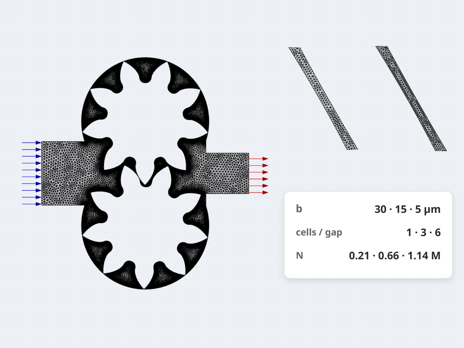
k-ε; triangular mesh with smoothing + remeshing so the gears can turn through micrometre gaps; 1 µs time
step.
- Boundary conditions from the test rig: 1 atm at suction, 21 atm at delivery, 6,000 rpm.
- Three validation steps: mesh independence (1, 3, 6 cells across the gap), 2D against 3D, and the smallest gap
between the teeth (30, 15, 5 µm) against the test.
Results
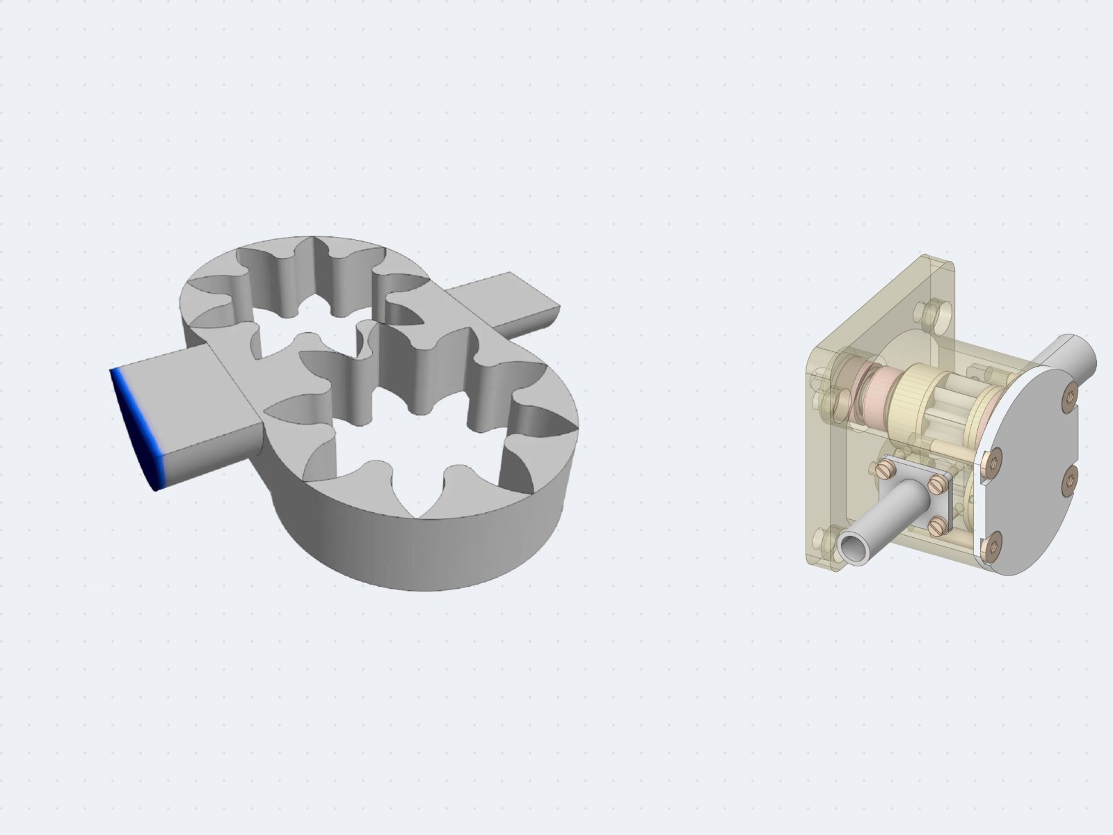
- The 2D and 3D models on the same mesh give 13.60 and 13.68 L/min — 0.6% apart — so 2D was chosen to cut run
time for the following cases. Two revolutions are enough to take the mean flow.
- The smallest gap between the teeth governs the flow: 30 µm gives −9.3% against the test, 15 µm +2.9%,
5 µm +6.7%. The ideal case takes 5 µm, since an ideal design and assembly should deliver more than the real
pump and come close to the theoretical flow (17.24 L/min from the actual geometry). The mean flow reaches
16.01 L/min.
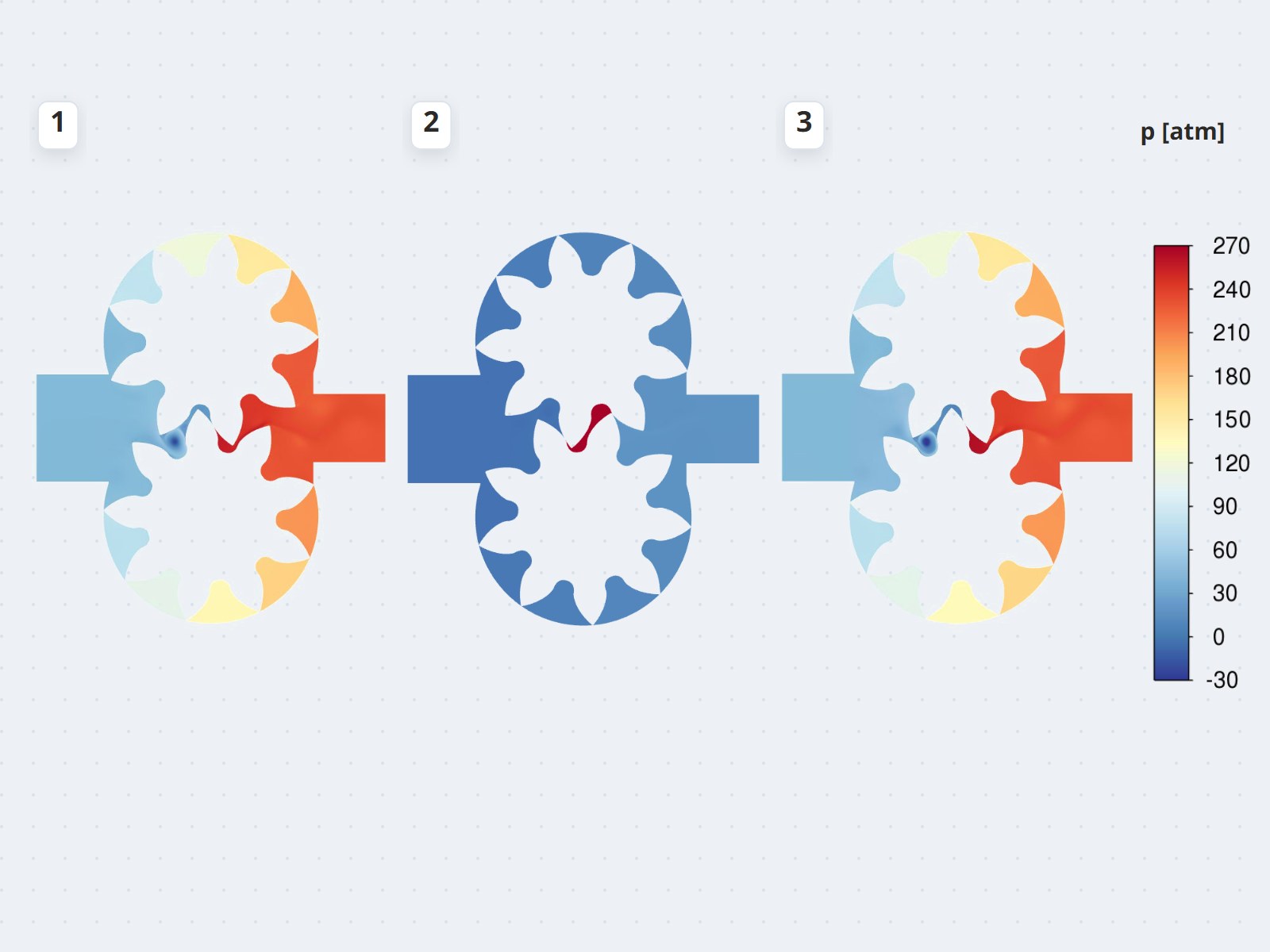
- The separating tooth space near the suction port drops below −3 atm — a risk of vaporisation and
cavitation.
- On the meshing side, liquid is trapped between two teeth (trapped volume): the pressure spikes and then
collapses within a very short time, risking surface damage, reduced fatigue life and noise. Recommendation:
add a pressure-relief groove.
Value
The validated model is the basis for phase 2: tip clearance, radial and axial eccentricity, surface roughness,
speed, the relief groove, and Jet A-1 viscosity varying with pressure and temperature — so that each
manufacturing tolerance can be expressed as flow and pressure before machining.