Context & problem
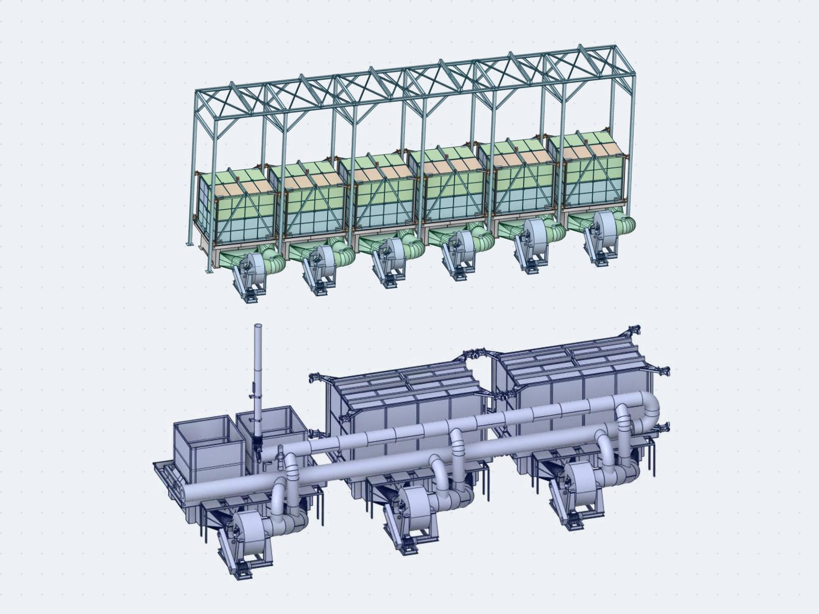
The new charcoal plant has 6 pyrolysis furnaces and 3 dryers sharing hot-gas, recycle-gas and exhaust ducts
that all end at exhaust fan FA10. With 3 furnaces and 2 dryers, the system runs stably; with a fourth furnace or the third dryer, batches run abnormally long. The plant needed to know whether the bottleneck was the
ductwork or the fan, and wanted to send the 110 °C exhaust gas to its old plant to recover the heat.
Approach
- Mass and energy balance for four scenarios (3+2, 4+2, 3+3, 4+3 furnaces + dryers): flow, velocity and
diameter of every main and branch duct, checked against the measured operating point of FA10 at 45 Hz.
- The wood charge in the furnaces and dryers modelled as a porous zone, with the resistance from the Ergun
equation (70 × 30 × 30 mm wood pieces, porosity 0.40).
- CFD of the complete duct network at full load (4 furnaces + 3 dryers, no heat loss) for the current ducts
and four layouts with new main-duct diameters; the branches connected to the equipment stay as built.
- Fan selection from the computed pressure loss, checked on the current ductwork; a fitting designed for FA10
running in series with the old plant's fan FA11 for heat recovery.
Results
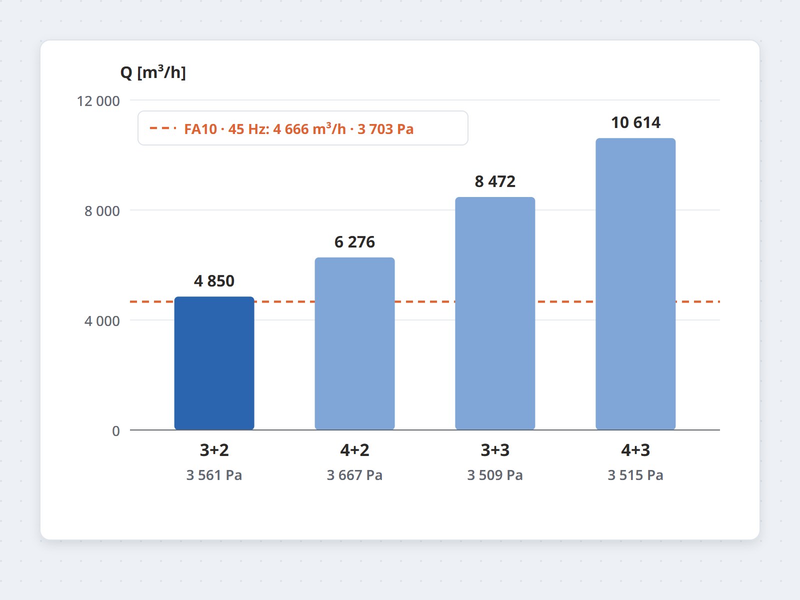
- Diagnosis: with 3 furnaces + 2 dryers the computed flow and pressure (4,850 m³/h, 3,561 Pa) match FA10 at
45 Hz (4,666 m³/h, 3,703 Pa). The other three scenarios need 6,276–10,614 m³/h, far beyond what the installed fan can deliver, consistent with the long batches observed at the plant.
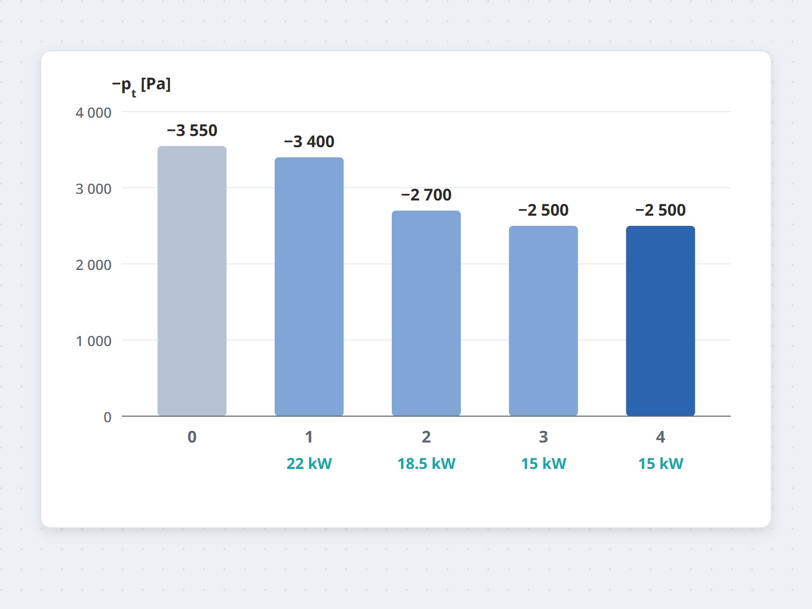
- Ductwork: total pressure at the fan inlet −3,550 Pa with the current ducts; −3,400, −2,700, −2,500 and
−2,500 Pa for designs 1–4. Design 4 was selected: it combines the first three and keeps the peak main-duct velocity below 25 m/s with 45° fittings.
- Fan: 11,800 m³/h, 4,200 Pa total at 50 Hz and 110 °C, trimmed by the VFD. On the current ductwork
it runs at about 45 Hz; with the new ducts it runs lower still. At start-up the frequency is ramped up
gradually so the motor is not overloaded while the gas is still cool.
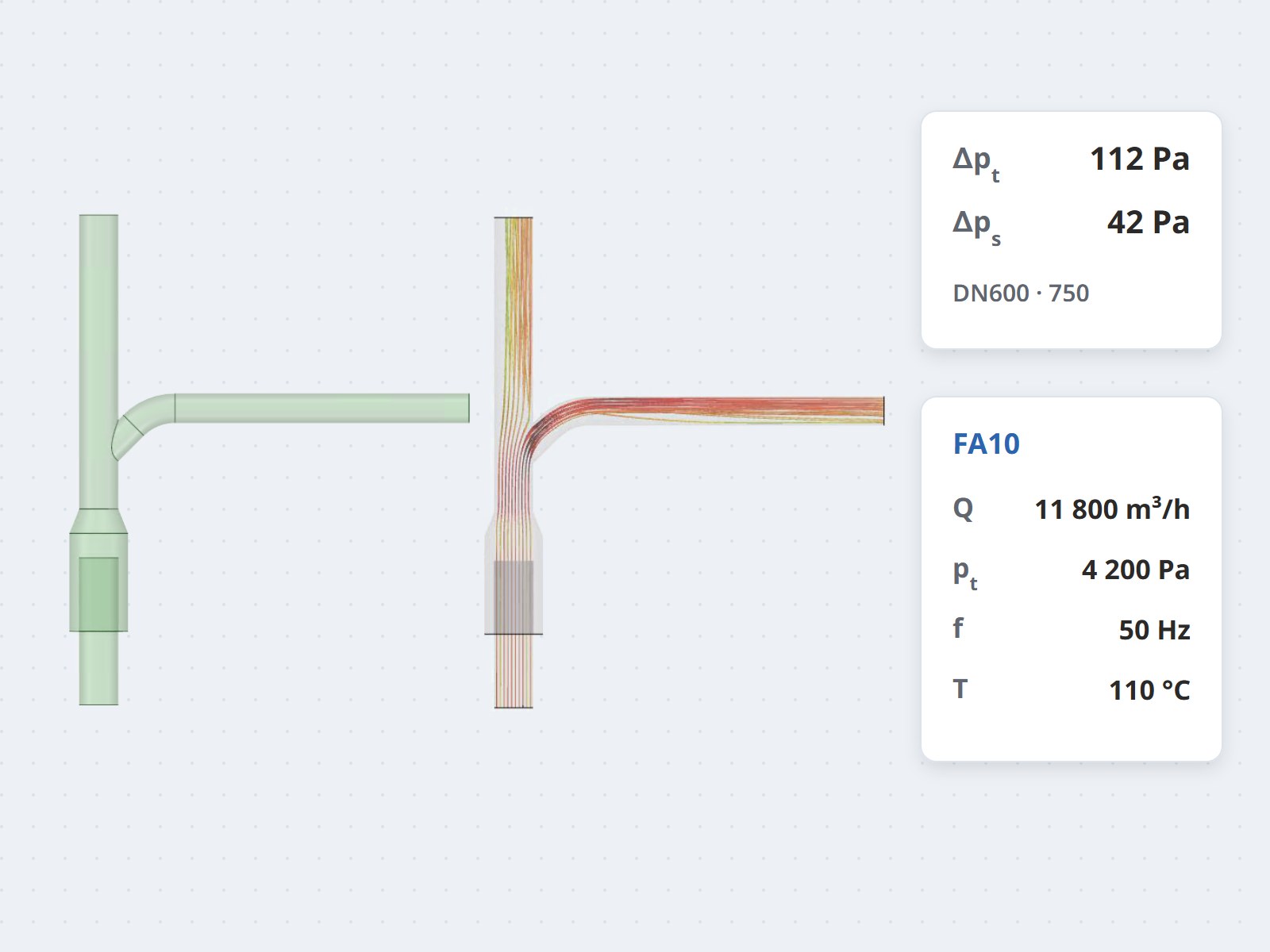
- Heat recovery: FA10 in series with FA11 (330 °C, 41,400 m³/h) risks being pushed into stall. A DN600 fitting
at the stack base with a damper, open to atmosphere to balance the flow: CFD gives a 112 Pa total
pressure loss and no backflow from ambient. The link between the plants goes from DN200 to DN300.
Value
The plant now has data identifying the cause of its long batches: the exhaust fan lacks flow in every high-load scenario.
The new fan works on the existing ductwork straight away; once the ducts are rebuilt to design 4 it runs at a
lower frequency. The heat-recovery branch to the old plant has its fitting and damper sized in advance, so the
two fans in series stay stable.